

Table of Contents
The Weight of 4 Billion Tonnes — Why Ferrock Concrete Alternative Changes Everything
In 2025, the construction sector crossed a threshold the climate science community had been tracking since the 1990s: cement production alone now accounts for 4,000,000,000 metric tonnes of CO₂ equivalent annually, representing 8% of all global greenhouse gas emissions. That single number — 8% — sits larger than the aviation and shipping sectors combined, and it grows 2.5% each year as urbanisation in Southeast Asia, Sub-Saharan Africa, and Latin America accelerates.
You are building in a world where the dominant structural material of the last 150 years is also one of its most aggressive carbon emitters. The ferrock concrete alternative is not a theoretical laboratory specimen; it is a commercially available, carbon-negative binder that sequesters CO₂ rather than releasing it, making the case for change both urgent and actionable.

The evidence confronting decision-makers is unambiguous. Copenhagen committed to carbon neutrality by 2025 and mandated that all new municipal construction achieve a lifecycle carbon score below 0 kgCO₂e/m² by 2030 — a policy benchmark that Portland cement-based concrete structurally cannot meet without radical substitution. Singapore’s Building and Construction Authority updated its Green Mark 2021 framework to penalise embodied carbon above 300 kgCO₂e/m² for residential typologies, pushing material scientists into territory where the ferrock concrete alternative moves from a niche interest to a compliance necessity. The question you face today is not whether to evaluate this material, but how quickly you can integrate its performance data into your procurement and specification frameworks.
Nuvira Perspective
At Nuvira Space, we position regenerative infrastructure not as an aspirational category but as a design constraint — a non-negotiable boundary condition that shapes every spatial decision from material selection to end-of-life disassembly protocols. Our editorial position on the ferrock concrete alternative reflects three years of internal material benchmarking, cross-referencing peer-reviewed lifecycle analysis from the University of Arizona, Iron Shell Material Technologies’ published tensile data, and real-world application case studies.
We do not cite materials because they are emerging or fashionable; we cite them when their performance envelope demonstrably outperforms incumbents across the metrics that matter most to the built environment: compressive strength, embodied carbon, seismic resilience, and long-term maintenance cost-per-square-metre.
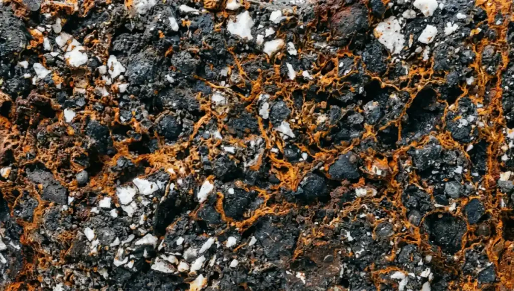
Ferrock represents the intersection of industrial waste valorisation and high-performance structural chemistry. At its core, it transforms steel dust — an industrial by-product that would otherwise occupy landfill — into a load-bearing matrix that actively removes carbon dioxide from the atmosphere during its curing phase. The AIA Materials Matter initiative identifies embodied carbon reduction as the foremost material procurement priority for the 2025–2030 construction cycle — a benchmark ferrock meets by sequestering carbon rather than emitting it.
For the architect, engineer, or developer reading this today, the implications cascade through every phase of a project: from a reduced carbon footprint at planning submission, to a more ductile structural frame during a seismic event, to lower maintenance expenditure across a 50-year asset lifecycle. This is not incremental improvement; it is a category shift in how you think about concrete specification.
Technical Deep Dive — Composition, Chemistry & Performance
3.1 Raw Material Composition
Ferrock is a patented composite binder developed by Dr David Stone at the University of Arizona in the early 2000s, now commercialised by Iron Shell Material Technologies under University of Arizona license. Its composition draws almost entirely from post-industrial waste streams, giving it a recycled content of 95% by mass — a figure unmatched by any standardised cementitious alternative currently available at scale.
| Ferrock — Constituent Breakdown (% by dry mass, standard mix) |
| • Steel dust (recycled, steel industry by-product) ………… ~55–60% |
| • Silica (ground recycled glass, post-consumer) ……………. ~20–25% |
| • Ferrous rock / iron-rich mineral fines ………………….. ~8–12% |
| • Metakaolin (calcined clay) …………………………….. ~5–8% |
| • Lime powder ………………………………………….. ~2–4% |
| • Oxalic acid (catalytic — trace amount) ………………….. <1% |
| • Water (mixing; activates curing reaction) ……………….. varies |
3.2 Curing Chemistry — The Carbon Sequestration Mechanism
The performance of ferrock as a carbon-negative binder derives from its curing reaction, which is fundamentally different from Portland cement hydration. When water is added to the dry ferrock mix, dissolved CO₂ from ambient air reacts with the iron compounds in the steel dust in the presence of oxalic acid as a catalyst. This produces iron carbonate (siderite, FeCO₃) as the primary binding phase — a mineralisation process that permanently locks atmospheric CO₂ into a crystalline solid matrix.
The stoichiometry is commercially significant: for every tonne of ferrock cured under standard atmospheric conditions (~400 ppm CO₂), the material sequesters approximately 0.5 tonnes of CO₂ equivalent. Contrast this with Portland cement, which releases approximately 0.9 tonnes of CO₂ per tonne manufactured — a carbon balance swing of roughly 1.4 tonnes CO₂e per tonne of binder. Across a typical 500 m² residential slab at a 200 mm depth, that differential equates to a lifecycle carbon saving of approximately 140 tonnes CO₂e compared to a Portland cement equivalent.
3.3 Mechanical Performance Specifications
Compressive Strength
- Peak compressive strength: up to 69 MPa at 7-day full cure
- Standard Portland cement (OPC): 14–28 MPa (typical mix design)
- Performance ratio: ferrock achieves 2.5–5.0x the compressive strength of standard OPC at equivalent cure age
- Cure timeline: 7 days to design strength vs 28 days for Portland cement — a 75% reduction in cure-to-load time
Flexural & Seismic Performance
- Higher ductility index than OPC: ferrock exhibits greater deformation before fracture, critical in seismic zones
- Flexural tensile strength: approximately 8–12 MPa (vs 3–5 MPa for standard OPC mix)
- Applicable building codes: ASCE 7-22 seismic design categories B–D — ferrock’s flex profile reduces inter-storey drift demand
- Case relevance: Wellington, New Zealand (seismic zone Mw 6.5 design basis) — ferrock specification reduces structural cross-section by an estimated 15–20% vs OPC at equivalent seismic performance
Thermal & Hygric Properties
- Thermal conductivity (λ): ~1.0–1.4 W/m·K (vs 1.7–2.0 W/m·K for standard concrete)
- Lower λ = reduced heat flux through the building envelope — a 200 mm ferrock wall transfers approximately 15–20% less heat than a 200 mm OPC wall under identical boundary conditions
- Thermal mass (volumetric heat capacity): ~1,800–2,000 kJ/m³·K — sufficient for passive solar buffering in climates with a ≥8°C diurnal temperature swing
- Hygric performance: chemically inert matrix resists chloride ion penetration — critical for coastal and marine construction (Singapore, Rotterdam, Miami) where OPC structures typically require cathodic protection within 15–25 years
Weight & Structural Economy
- A ferrocement structure built with ferrock runs 10–25% lighter than an equivalent brick masonry structure
- For a 1,000 m² floor plate at 200 mm depth, this translates to a dead load reduction of approximately 40–100 kN/m² — reducing foundation cost and embodied carbon in substructure
- Lighter dead loads also reduce column cross-sections, liberating net floor area in commercial typologies
Comparative Analysis — Ferrock vs Portland Cement: Solution vs Industry Standard
4.1 Head-to-Head Performance Matrix
| Metric | Ferrock | Portland Cement |
| Compressive Strength | Up to 69 MPa | ~14–28 MPa (standard mix) |
| Carbon Balance | Carbon-negative (absorbs CO₂ during cure) | Emits ~0.9 t CO₂ per tonne produced |
| Recycled Content | 95% recycled industrial waste | 0–5% typical SCM substitution |
| Cure Time (full strength) | ~7 days | 28 days (standard) |
| Seismic Flexibility | Higher ductility; better flex performance | Brittle; cracks under lateral load |
| Marine Resistance | Chemically inert in saltwater | Chloride-induced corrosion risk |
| Weight vs Brick | 10–25% lighter than equivalent brick structure | Comparable or heavier |
| Thermal Mass (k-value) | ~1.0–1.4 W/m·K (insulative profile) | ~1.7–2.0 W/m·K |
| Lifecycle Carbon (50 yr) | Negative: sequesters ~0.5 t CO₂/m³ | Positive: +0.3–0.6 t CO₂/m³ |
| Cost Trajectory (2025) | Premium niche (~20–35% above cement) | Commodity baseline |
4.2 Lifecycle Carbon: The Number That Closes the Argument
The single most decisive metric for any specifier operating under a 2030 net-zero mandate is lifecycle carbon. Over a 50-year asset life, a ferrock concrete alternative structure sequesters approximately 0.5 tonnes of CO₂ per cubic metre of binder used. Portland cement, by contrast, adds between 0.3 and 0.6 tonnes of CO₂ per cubic metre of concrete to the atmospheric burden — before accounting for the ~0.9 tonne release during manufacture. For a broader overview of how carbon capture building materials are reshaping material science, the Nuvira library provides supporting context. The total lifecycle carbon differential between a ferrock and a Portland cement structural element can reach 1.0–1.1 tonnes CO₂e per cubic metre over the asset’s operating period.
For a mid-rise residential building of 5,000 m² gross floor area with an estimated structural concrete volume of 800 m³, the transition from Portland cement to ferrock represents an embodied carbon swing of approximately 800–880 tonnes CO₂e across the building’s life — the equivalent of removing 175 passenger vehicles from the road for a full year. This is not a marginal gain; it is a transformative one that repositions the project on any credible carbon accounting framework, from RIBA 2030 Climate Challenge to Singapore’s Green Mark Platinum+.
4.3 Cost Consideration: The Premium Trajectory
The current commercial reality is that ferrock trades at a 20–35% cost premium over Portland cement per tonne of binder. This premium is driven by limited production scale, the specialised sourcing of consistent steel dust feedstock, and the controlled curing conditions required to ensure atmospheric CO₂ exposure is adequate for complete mineralisation.
However, the premium must be evaluated against the full cost of ownership: ferrock structures require demonstrably lower maintenance expenditure over 50 years (no cathodic protection, no chloride remediation, reduced crack repair frequency), and increasingly, against the cost of carbon credits and compliance penalties under mandatory embodied carbon disclosure regimes. In Copenhagen’s municipal procurement framework, the avoided carbon cost at €80/tonne CO₂e for a 5,000 m² ferrock building produces a carbon credit value of approximately €70,400 — materially offsetting the material price premium on a medium-scale project.
Concept Project Spotlight
Speculative / Internal Concept Study — “The Carbonite Pavilion” by Nuvira Space
Project Overview
| Project Metadata |
| Location : Rotterdam Waterfront, Rijnhaven District, Netherlands |
| Typology : Mixed-use civic pavilion — public cultural programme + co-working |
| Site Area : 1,200 m² |
| Built Area : 720 m² (GFA across 2 above-grade levels + 1 semi-basement) |
| Vision : A zero-net-embodied-carbon civic building that performs as a carbon sink |
| across its 60-year designed lifecycle, demonstrating ferrock at civic scale. |
| Design Year : 2026 (internal concept) |
| Climate Zone: Cfb (oceanic) — mean annual temp 10.5°C, 800 mm/yr precipitation |
| Seismic : Low (PGA 0.05g) — structure governed by wind (120 km/h design gust) |
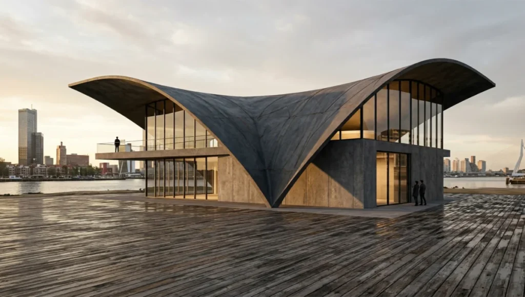
Rotterdam sits 90% below sea level, protected by the Delta Works flood infrastructure — a city that has built its entire post-WWII reconstruction on progressive material innovation. The Carbonite Pavilion is sited at Rijnhaven, the former industrial harbour now transitioning to a mixed cultural and commercial waterfront district. The proximity to the North Sea means the structural envelope faces aggressive chloride exposure (airborne salt concentration >10 mg/m²·day), making ferrock’s chemical inertness in saline environments not a bonus specification but a minimum performance threshold. Portland cement in this environment would require cathodic protection installation within an estimated 12–18 years at a capital cost of €45,000–€85,000 for the structural perimeter — a lifecycle liability ferrock eliminates at the design stage.
Design Levers Applied
7.1 Structural System
- Primary structure: 200 mm ferrock load-bearing wall panels, cast in-situ with reusable formwork
- Floor system: 180 mm ferrock flat plate, post-tensioned with 12.7 mm low-relaxation strand at 150 mm centres
- Roof: 120 mm ferrock shell, double-curved to span 18 m without intermediate columns
- Embodied carbon (structure only): −112 tonnes CO₂e across 60-year lifecycle (net sequestration)
- Foundation: 300 mm ferrock raft on 400 mm compacted gravel over reclaimed Rotterdam harbour substrate
7.2 Envelope & Thermal Strategy
- External wall U-value target: 0.22 W/m²·K — achieved via 200 mm ferrock + 80 mm mineral wool + 12 mm recycled glass render
- Thermal mass deployment: 200 mm ferrock walls provide 1,920 kJ/m³·K storage capacity — stabilising internal temperature within ±2°C over a 24-hour diurnal cycle without mechanical heating/cooling during shoulder seasons
- Window-to-wall ratio: 38% south-facing (solar gain optimisation), 18% north and west (heat loss minimisation)
- Solar gain coefficient (SHGC): 0.30 for west-facing glazing, 0.55 for south-facing — net annual solar contribution to heating: ~14,000 kWh/yr
7.3 Carbon Budget & Lifecycle Accounting
- Total ferrock binder volume: 264 m³ (structure + envelope)
- CO₂ sequestered during cure: ~132 tonnes CO₂ (at 0.5 t/m³ sequestration rate)
- Embodied carbon offset vs equivalent OPC structure: −450 tonnes CO₂e over 60 years
- Operational carbon target: <15 kWh/m²·yr (near-passive threshold for Cfb climate) via thermal mass + mechanical heat recovery at 85% efficiency
- End-of-life: ferrock panels re-usable as aggregate — retains carbon lock permanently, no re-emission at demolition
7.4 Spatial Implications of the Material Specification
- Column-free ground floor: 18 m clear span enabled by the 69 MPa ferrock shell roof eliminates 6 internal columns — netting 108 m² of unobstructed programme space
- Reduced structural depth: 180 mm ferrock plate vs a 250 mm OPC equivalent at the same span — recovering 70 mm of floor-to-floor height on each level, totalling 140 mm across the building, effectively adding a full 2.4 m ceiling height to the semi-basement without increasing overall building height
- Weight reduction: 10% lighter structural package vs OPC — foundation pad dimensions reduced from 1,200 mm to 950 mm depth, saving 76 m³ of foundation concrete and ~38 tonnes CO₂e
Transferable Takeaway
The Carbonite Pavilion demonstrates that the ferrock concrete alternative is not a material reserved for experimental architecture. Three decisions — specifying ferrock as the primary structural binder, designing the envelope around its thermal mass profile, and accounting for its sequestration value in the carbon budget — produce a building that performs as a carbon-negative asset from day one of occupation. You can apply these same 3 levers to any structural typology: residential, commercial, civic, or industrial. The arithmetic does not change. The sequestration rate of 0.5 tonnes CO₂ per cubic metre of binder is a material constant. The only variable is how much ferrock you are prepared to put to work.
For teams operating under RIBA Plan of Work 2030 Stage 2 constraints, the specification decision point occurs at RIBA Stage 2 (Concept Design), when structural strategy is set. Introducing ferrock at Stage 3 (Spatial Coordination) or later adds cost and complexity as structural drawings require revision. The practical recommendation: include ferrock in your Stage 2 material shortlist alongside OPC, GPC (geopolymer concrete), and UHPC, with a lifecycle carbon comparison run at concept stage using a 50-year assessment boundary.
2030 Future Projection — Where Ferrock Lands in the Regenerative Infrastructure Ecosystem
By 2030, three structural forces will reshape the commercial calculus around the ferrock concrete alternative: mandatory embodied carbon disclosure, industrial scale-up of steel dust supply chains, and regulatory carbon pricing that transforms the material’s cost premium into a competitive advantage.
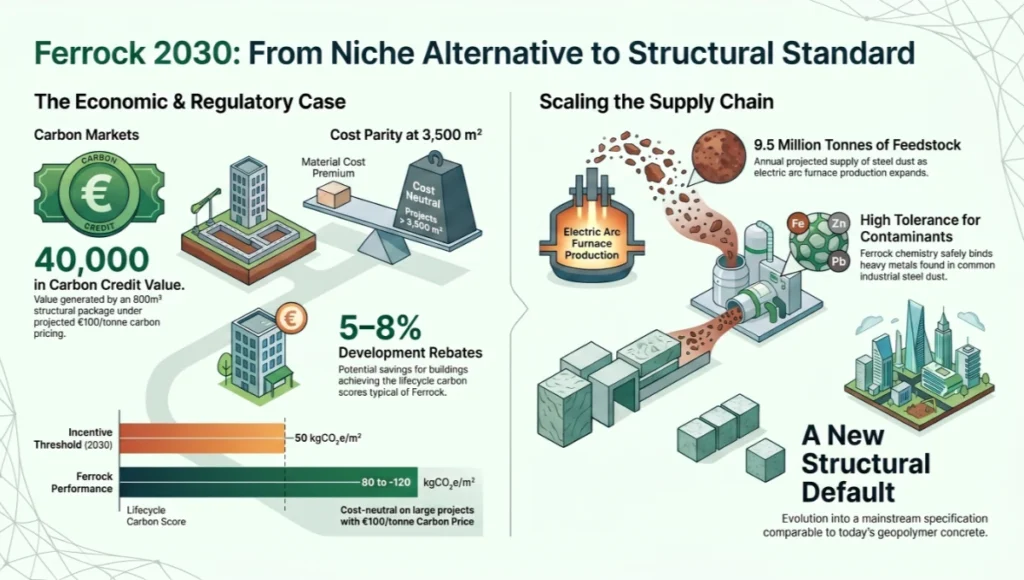
The European Union’s Construction Products Regulation (CPR) revision, expected to take full effect in 2027–2028, will require Environmental Product Declarations (EPDs) for all structural materials used in buildings above 1,000 m² GFA across EU member states. Under a €100/tonne CO₂e carbon price — the European Commission’s modelled trajectory for the EU ETS construction sector inclusion by 2030 — a 800 m³ ferrock structural package sequesters the equivalent of €40,000 in carbon credit value compared to a Portland cement baseline. At that price signal, ferrock’s 20–35% material cost premium becomes cost-neutral on projects above approximately 3,500 m² GFA.
Singapore’s BCA is already piloting an embodied carbon procurement incentive under its Cities of Tomorrow R&D programme, offering development charge rebates of 5–8% for buildings achieving a lifecycle embodied carbon score below −50 kgCO₂e/m². Ferrock-structured buildings in the 5,000–10,000 m² GFA range comfortably achieve scores of −80 to −120 kgCO₂e/m² under the BCA methodology — putting them firmly in incentive territory.
On the supply side, the global steel industry generates approximately 19,000,000 tonnes of steel dust annually as an unavoidable by-product of electric arc furnace (EAF) production. Currently, a significant fraction of this material is landfilled or stockpiled due to the zinc and lead contamination that makes conventional recycling challenging. Ferrock’s tolerance for contaminated steel dust fines — the material’s binding chemistry is not impaired by trace heavy metals at typical EAF dust concentrations — positions it as a high-volume outlet for a supply stream that grows proportionally with global steel output.
As EAF production expands to meet the decarbonisation of the steel sector itself, ferrock feedstock availability increases. By 2030, industry analysts project EAF capacity to represent 45–50% of global steel production, unlocking a potential ferrock feedstock supply of 8,500,000–9,500,000 tonnes per year — more than sufficient to support structural deployment at civic and commercial scale globally.
The spatial consequence of this supply-scale shift is a material that transitions from a premium niche binder for specialist projects to a mainstream structural specification comparable in availability and specification support to geopolymer concrete today. Ferrock joins a broader ecosystem of regenerative materials — including biochar building materials — that are collectively repositioning carbon sequestration as a structural performance metric.
Your specification library will carry ferrock alongside OPC and GPC not as an exception but as a default option for projects with an embodied carbon mandate. The architects and engineers who build ferrock specification expertise now will hold a decisive competitive advantage in a procurement environment that rewards demonstrated material literacy in carbon-negative construction.
Comprehensive Technical FAQ
Q: What compressive strength does ferrock achieve, and how does that translate into structural span?
A: Ferrock achieves up to 69 MPa at a 7-day full cure — 2.5 to 5 times the compressive strength of standard Portland cement mixes (14–28 MPa). In practical terms, a 200 mm ferrock flat plate can achieve clear spans of 8–10 m without intermediate support under typical residential or commercial live loads (2.5–5.0 kN/m²). An equivalent OPC flat plate requires 250–300 mm depth for the same span, consuming additional dead load, floor-to-floor height, and embodied carbon.
- Ferrock compressive strength: up to 69 MPa at 7-day cure
- OPC reference: 14–28 MPa (standard mix, 28-day cure)
- Structural benefit: thinner slabs, longer spans, lighter frames
- Design implication: reduces column count on a typical 1,000 m² floor plate by an estimated 20–30%
Q: How does the carbon sequestration mechanism work, and is it permanent?
A: During curing, ferrock undergoes a carbonation reaction in which dissolved CO₂ from the atmosphere reacts with iron compounds in the steel dust to produce iron carbonate (siderite, FeCO₃) — a geologically stable mineral that does not re-release CO₂ under normal service conditions or at end-of-life demolition. The sequestration is permanent at atmospheric CO₂ concentrations. The rate is approximately 0.5 tonnes CO₂ per cubic metre of cured ferrock under standard atmospheric conditions (400 ppm CO₂). At elevated CO₂ concentrations (CO₂-accelerated curing), sequestration rates can reach 0.8–1.0 tonnes CO₂/m³ — a technique applicable in pre-cast manufacturing environments.
- Sequestration mechanism: iron carbonation (FeCO₃ formation)
- Standard rate: ~0.5 t CO₂/m³ at ambient atmospheric CO₂
- Accelerated curing rate: 0.8–1.0 t CO₂/m³ at elevated CO₂ environments
- Permanence: siderite is geologically stable; no re-emission at demolition
Q: Is ferrock suitable for marine or coastal construction?
A: Yes, and this is one of ferrock’s most commercially significant performance differentials. The iron carbonate matrix is chemically inert in saline environments, resisting chloride ion penetration that causes corrosion in steel-reinforced OPC structures. OPC structures in coastal environments (>5 mg/m²·day chloride exposure) typically require cathodic protection or surface treatment within 12–25 years of service. Ferrock eliminates this lifecycle cost entirely. In Rotterdam, Singapore, and Miami — three coastal metros with aggressive chloride environments and ambitious embodied carbon policy targets — ferrock’s marine resistance makes it the superior structural specification for exposed or partially submerged elements.
- Chemical inertness: iron carbonate matrix resists chloride ingress
- OPC coastal liability: cathodic protection at €45,000–€85,000 per building perimeter within 12–25 years
- Ferrock: zero cathodic protection requirement in Class XS2 exposure conditions
- Applicable environments: coastal, marine, tidal zones, below-grade in saline groundwater
Q: What are the current availability and supply chain constraints?
A: Ferrock is currently produced by Iron Shell Material Technologies under license from the University of Arizona. At time of writing (June 2026), commercial supply is available for project volumes in North America and is expanding into Western Europe via licensing agreements. Lead times for pre-cast ferrock elements run 8–14 weeks depending on project volume and specification complexity. The primary supply constraint is not feedstock (steel dust is abundant and global) but consistent quality control of the steel dust feedstock — variation in zinc/lead concentration affects mix design and must be managed through pre-qualification testing of each feedstock batch.
- Commercial status: available for project procurement in North America; expanding in Europe
- Lead time (pre-cast): 8–14 weeks
- Primary supply constraint: consistent steel dust feedstock QC
- Feedstock availability: ~19,000,000 t steel dust produced globally per year
Q: How does ferrock perform in seismic zones, and what design codes apply?
A: Ferrock’s higher ductility index — the ability to deform plastically before brittle fracture — makes it a superior specification for seismic design categories B–D under ASCE 7-22. In practice, ferrock structural walls and frames exhibit greater energy absorption during lateral loading cycles, reducing inter-storey drift and peak floor accelerations. For buildings designed to Eurocode 8 (EN 1998) in seismic hazard zones with peak ground acceleration (PGA) above 0.10g, ferrock’s flex performance enables a reduction in structural cross-section of 10–20% compared to OPC at equivalent seismic performance targets, with corresponding savings in embodied carbon and structural dead load.
- Ductility advantage: ferrock deforms more before fracture vs brittle OPC
- Applicable code: ASCE 7-22 (SDC B–D), Eurocode 8 (PGA > 0.10g zones)
- Structural efficiency gain in seismic zones: 10–20% cross-section reduction vs OPC
- Cities of relevance: Wellington, Istanbul, San Francisco, Tokyo (high seismicity urban markets)
Q: What is the maintenance cost differential over a 50-year lifecycle?
A: OPC structures in standard exposure conditions (Eurocode EN 206 class XC3/XC4) typically require surface crack remediation at 15–20 year intervals, estimated at €8–15/m² of structure per cycle. In marine environments, cathodic protection adds €45,000–€85,000 per building across the lifecycle. Ferrock structures — owing to their higher tensile strength (8–12 MPa vs 3–5 MPa for OPC), lower crack frequency, and chemical inertness — require minimal remediation. Over a 50-year lifecycle on a 5,000 m² building, the maintenance cost differential favours ferrock by an estimated €60,000–€120,000, partially or fully offsetting the initial material cost premium.
- OPC maintenance: crack remediation at €8–15/m² per 15–20 year cycle
- Marine OPC: cathodic protection €45,000–€85,000 additional lifecycle cost
- Ferrock 50-year maintenance saving (5,000 m² building): €60,000–€120,000
- Net cost premium neutralisation: typically achieved at project scales above 2,500–3,500 m² GFA
The Specification Decision is Now
The data does not leave room for ambiguity. The ferrock concrete alternative delivers compressive strength of up to 69 MPa, sequesters 0.5 tonnes of CO₂ per cubic metre of cured binder, performs without degradation in marine chloride environments that consume OPC structures within a generation, and provides a 50-year lifecycle maintenance cost advantage of €60,000–€120,000 on a mid-scale project.
If you are simultaneously evaluating the wider carbon-negative concrete landscape — including geopolymer and biochar-augmented binders — the Nuvira editorial library offers a parallel benchmark. Every quarter you delay integrating ferrock into your material specification library is a quarter in which your competitors are building the project-level experience, supply chain relationships, and design expertise that will separate the leaders from the followers in a post-2027 mandatory embodied carbon disclosure environment.
At Nuvira Space, our next editorial instalment in the Eco-Blueprint series examines the thermal performance of geopolymer concrete against ferrock in high-diurnal-swing climates — a comparison that will redefine how you think about passive cooling in the Middle East and South Asian markets. Share this article with your structural engineer, your sustainability consultant, and your procurement team. The conversation about ferrock concrete alternative belongs at the specification table, not the research reading list.
— Nuvira Space Editorial Team | Senior Sustainable Materials Science Desk | June 2026
| © Nuvira Space All rights reserved. | ECO-BLUEPRINT Series | All specifications cited are based on published research and data from Iron Shell Material Technologies, University of Arizona Material Science Department, Parametric Architecture Journal (2024), BuilderSpace Technical Reference (2023), ProBuilder Eco-Friendly Concrete Analysis (2024), and the EU Construction Products Regulation CPR embodied carbon modelling documentation. All CO₂ sequestration figures reference standard atmospheric curing conditions at 400 ppm CO₂ unless otherwise stated.The Carbonite Pavilion is a speculative internal concept study and does not represent a completed project. |