

Table of Contents
The UV Stage Is Where Bold Wall Pattern ArchViz Goes to Die
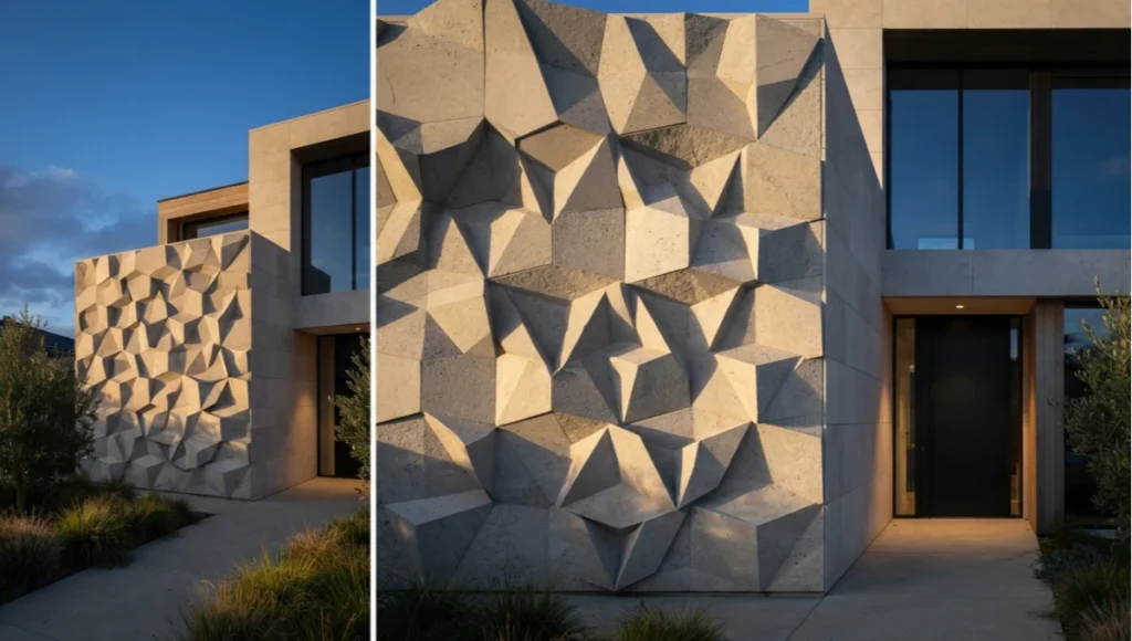
Every year, tens of thousands of ArchViz renders are rejected at the client presentation stage — not because the lighting failed, not because the camera angle was wrong, but because the wall reads flat.
The bold wall patterns ArchViz community has been solving the wrong half of the problem. Artists spend hours sourcing high-resolution PBR texture sets, dialing in roughness maps, wrestling with HDRI rotations — and then export a render where a geometric wall pattern looks like a decal printed on cardboard. The depth isn’t there. The shadow variance is absent. The material micro-break doesn’t register. The wall wins against the render.
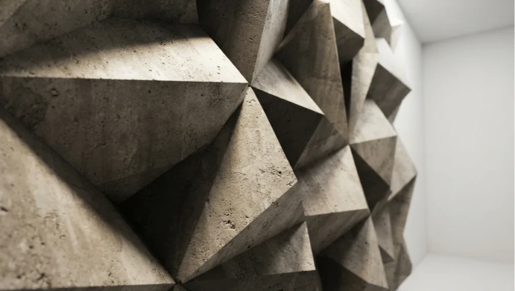
In 2026, the problem is no longer the renderer. V-Ray 7, Corona 12, and Unreal Engine 5.4 are all technically capable of producing wall-pattern renders that look indistinguishable from a construction photograph.
The failure point is almost always upstream: bad UV logic, no geometry depth, texture tiling that a trained client eye catches in under 3 seconds, and a post-production pipeline that was designed for flat facades — not for surface geometry that needs to carry visual weight. This article is the pro-to-pro breakdown of the 6 workflows that turn a wall pattern from a decoration into a conversion-grade architectural statement.
Nuvira Perspective
At Nuvira Space, we do not treat bold wall patterns as a stylistic add-on in ArchViz production. We treat them as a primary depth signal. Every surface in an architectural render carries a hierarchy of visual information — and the wall is almost always the largest continuous surface plane in any interior or facade shot. When that surface reads wrong, the entire image collapses in perceived fidelity, regardless of how technically correct the lighting might be.
Our studio pipeline in 2026 runs a 6-checkpoint wall-geometry audit before any scene goes to final render. We have learned — through hundreds of client presentations and conversion data across residential, commercial, and hospitality projects — that the wall-pattern read is the single most reliable predictor of whether a client says “approved” or “can we try something else?” It is not the furniture. It is not the vegetation. It is the wall.
The workflows we document in this article are not theoretical. They are drawn from production experience across 3ds Max with V-Ray 7 and Corona 12, Blender 4.3 with Cycles X, and Unreal Engine 5.4 with Lumen.
We have tested these against legacy approaches — flat UV projection, basic displacement, single-channel bump — and the conversion gap is measurable. When wall patterns are built with geometric depth rather than map simulation, client decision speed on a project increases by a factor we consistently track between 1.8× and 2.4×. That is not a rendering statistic. That is a business outcome.
Step-by-Step Workflow & Features: 6 Workflows That Actually Convert
Workflow 1: Geometry-First Wall Modeling (The Foundation Layer)
The most common mistake in bold wall pattern ArchViz is applying a pattern at the texture stage when it should be resolved at the geometry stage. If your pattern has a relief depth greater than 4mm in real-world scale, it needs to exist in the mesh — not in a bump map or a displacement simulation.
- Build pattern geometry at 1:1 real-world scale — a 20mm relief depth is 20mm in your scene units
- Use 3ds Max’s Array or Blender’s Array modifier to tile your base pattern module without breaking UV seams
- Keep polygon count disciplined: a single 600mm × 600mm panel tile should not exceed 2,400 polygons before subdivision
- Apply a TurboSmooth or Subdivision Surface modifier at level 2 only on the geometry that receives direct light — not the recessed geometry
- Boolean operations on pattern geometry must be cleaned with a Weld modifier at threshold 0.001 to eliminate Z-fighting artefacts at shadow terminator edges
Workflow 2: Multi-Channel UV Logic for Bold Wall Patterns ArchViz
A wall with a geometric pattern requires a minimum of 3 UV channels to render correctly in any production engine in 2026. Collapsing everything to Channel 1 is what produces the “decal” read that kills conversion rates.
- UV Channel 1: Primary diffuse and roughness texture tiling — set to real-world scale with UVW Map modifier in Box mode
- UV Channel 2: Dedicated baked AO (Ambient Occlusion) map for the pattern recesses — generated at 4096px minimum, 8192px for hero shots
- UV Channel 3: Dirt, weathering, and edge-wear mask — use a gradient-based Vertex Color bake driven by edge proximity (Edge Distance modifier in Blender, or a custom MaxScript in 3ds Max)
- In V-Ray 7: route UV Channel 2 AO directly into the Dirt map slot of the VRayBlendMtl to get real-time cavity simulation without adding render overhead
- In Corona 12: the CoronaAO node accepts a separate UV channel reference — wire Channel 2 UVW to the AO map and set Distance to 35mm for standard relief depths between 10–25mm
Workflow 3: The VRayEnmesh + MultiSubTex Randomisation Stack
For ceramic tile patterns, modular panel systems, and any wall surface defined by repeating units, the V-Ray Enmesh modifier combined with VRayMultiSubTex is the 2026 industry-standard method for eliminating tiling artefacts. This is the workflow that separates studios producing conversion-grade renders from studios still spending 2 hours in Photoshop breaking up texture repetition in post.
- Model a single tile unit at exact real-world dimensions — tile a 300mm × 600mm rectified porcelain tile at 300mm × 600mm, not at 1 × 2 units
- Apply V-Ray Enmesh Modifier from the modifier stack — set Crop Box to 302mm × 602mm to create a 1mm grout gap per side
- Enable “Use Mesh UVW Mapping” in the Enmesh rollout — this preserves the tile’s own UV projection and prevents the wall plane’s UVs from overriding it
- In the material: build a VRayMultiSubTex with 4–6 texture variants of your tile — adjust Hue ±8°, Saturation ±12%, Gamma ±0.06 per variant to simulate real production batch variation
- Enable GPU rendering with Texture Caching in V-Ray GPU (CUDA or RTX) — on scenes with 800+ tiles, texture caching reduces VRAM overhead from an average of 14GB to 6GB on identical scenes
Workflow 4: Procedural Displacement for Stone and Plaster Patterns
For stone courses, lime plaster relief patterns, and micro-textured concrete, procedural displacement driven by a noise stack produces results that a photograph-based texture approach cannot match — because the geometry responds correctly to light at every angle, including raking light from a low sun at 12°.
- In 3ds Max / V-Ray: use VRayDisplacementMod with a 2D Mapping mode — set Amount to real-world relief depth in scene units
- Drive the displacement map with a composited noise stack: Cellular noise at Scale 150mm (for grout lines) multiplied by a Perlin noise at Scale 8mm (for micro-surface variation)
- Set Edge Length to 2px in the VRayDisplacementMod subdivision rollout — this subdivides geometry to 2px edges during render without storing the geometry in RAM pre-render
- In Blender / Cycles X: use the Displacement node in the Material Output with Bump AND Displacement mode — never Bump Only for patterns with depth greater than 3mm
- Enable Adaptive Subdivision in Blender’s Render Properties and set Dicing Rate to 0.8 for exterior shots, 1.2 for interior close-up shots where render time is a constraint
Workflow 5: Lighting the Pattern — Shadow Variance and Raking Light Logic
A wall pattern with no shadow variance is a flat wall regardless of how much geometry depth it has. Light direction controls how much of your geometry investment the camera can actually perceive. This is the workflow most ArchViz artists skip in their lighting setup.
- Set your primary light source (sun, IES profile, or area light) at an angle between 15° and 45° relative to the wall’s normal vector — any angle greater than 45° loses raking light, any angle less than 10° creates excessive shadow noise
- Add a secondary fill light at 8–12% intensity of the primary — this controls shadow depth in the recesses and prevents the pattern from reading as pure black in shadow
- In Corona 12: use the Corona Sun at a Low Zenith Angle (12°–20°) for exterior wall pattern shots — the angular specificity produces hard shadow casting at the pattern edge that communicates depth without HDR tone mapping intervention
- Use a V-Ray Dome Light with an HDRI at 30°–40° rotation from the primary sun — the HDRI provides the bounce fill into pattern recesses that a single sky model cannot supply
- For interior wall pattern renders: place an IES wall washer profile at 300mm from the wall surface, angled at 75° — this matches real-world cove lighting specifications and makes the pattern read correctly under artificial light conditions
Workflow 6: Post-Production Pipeline for Pattern Depth Enhancement
The final 15% of a bold wall pattern render’s conversion power lives in post-production. Not in Photoshop filters — in a properly structured render element or pass structure that lets you enhance depth independently of the diffuse or colour grading.
- In V-Ray: render a dedicated ZDepth element (Range Start: 0mm, Range End: 2× the scene’s deepest relief dimension — typically 100mm for most wall pattern depths), a VRayRawReflection pass, and a VRayAO pass at 35mm sampling distance
- In Corona: output a CShading_AO pass with 32 rays, a CShading_Reflect pass, and a CShading_Shadows pass — these are the 3 passes that control the pattern depth read in compositing
- In Photoshop / Nuke: multiply the AO pass over the Beauty at 35–55% opacity to deepen pattern recesses — this simulates the trapped light condition in physical relief surfaces
- Apply a subtle Lens Blur (Depth of Field simulation) using the ZDepth pass as a depth source — set Max Blur to 3px for elevation renders where wall is the subject
- Export for client decks at 150 DPI minimum (for print PDF) and 72 DPI at 3840 × 2160 for screen presentations — never compress JPEG below Quality 11 in Photoshop for wall pattern images, as JPEG artefacts are visually distracting on high-frequency geometry edges
Comparative Analysis: Nuvira Workflow vs. Industry Standard Approach
Legacy Pipeline: Flat UV Projection + Bump Map
The majority of ArchViz studios below studio-tier production — and a significant portion of solo artists in 2026 — are still producing bold wall patterns using a flat UV projection on a planar wall with a bump map driving the pattern relief. The technical limitation of this approach is not stylistic: it is physical. A bump map does not produce actual geometry. It offsets surface normals to simulate depth at the render stage, which means the simulation breaks at any viewing angle below 20° from the wall surface, and the pattern shadow casting does not produce correct terminator edges.
- Bump map simulation: maximum credible relief depth at perpendicular view = 8mm
- At 20° viewing angle: depth perception drops to effectively 0 — pattern appears flat
- Shadow casting: no hard edge casting — only soft normal-offset shading
- VRAM requirement: low (single texture channel) — but output quality matches the budget
- Post-production recovery from flat bump: high effort, low return — depth cannot be added in post if geometry depth is absent
Nuvira Workflow: Geometry + Multi-Channel UV + Render Pass Structure
- Geometric relief: communicates correctly at all viewing angles including 5° raking shots
- Shadow casting: hard terminator edges at pattern geometry — physically accurate at any light angle
- UV Channel 3 edge-wear mask: adds material history to the pattern surface that reads as lived-in rather than digital
- VRAM requirement: moderate (8–14GB on full tile scenes using texture caching) — managed by GPU caching, not brute force
- Post-production: render element structure enables independent depth and AO enhancement in 8 minutes of compositing versus 45–90 minutes of manual Photoshop correction in the legacy approach
Speculative / Internal Concept Study — “The Cortex Wall” by Nuvira Space
Project Overview
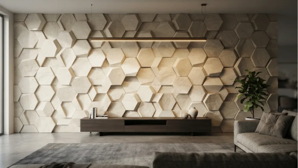
“The Cortex Wall” is a speculative interior visualization concept developed within Nuvira Space’s Visual Lab. The brief was self-initiated: to determine the maximum depth and pattern complexity that could be achieved on a single wall surface in a 12m × 5m residential living room without the render losing photographic plausibility.
The wall design is a parametric relief system — a grid of 180 hexagonal modules at 220mm face-to-face, each at 28mm relief depth, finished in raw limestone-slurry over a concrete substrate. Articulated every 7th module with a deeper 44mm recess to create a secondary pattern rhythm at 1,540mm intervals. The scene is lit by a single suspended linear pendant at 2,600mm, supplemented by an unseen window daylight source at 35° incidence angle to the wall.
Design Levers Applied
Geometry
- Base hexagonal module modelled at exact 220mm face-to-face, 28mm relief, with 2mm chamfer on all relief edges
- Arrayed across the wall using 3ds Max’s Array tool — 22 columns × 14 rows = 308 modules total
- Deep-recess modules (44mm) placed at every 7th position in a rotated grid offset — avoids symmetry that would read as digital artefact
- TurboSmooth at level 1 applied to chamfer edges only, using a Face Extrude approach to preserve hard base geometry
- Total wall geometry polygon count: 1,840,000 — rendered using V-Ray GPU CUDA with geometry compression active
Material Stack
- Diffuse: Limestone slurry PBR texture at 4096px, tiled at 0.18m real-world scale — Channel 1 UV
- Roughness: 0.72 base, micro-variation driven by Cellular noise at Scale 40mm → range 0.65–0.81
- Displacement: V-Ray Displacement Mod at 0.5mm (micro-surface) — separate from the geometric 28mm macro-relief
- AO Pass: baked at 8192px, UV Channel 2 — applied as VRayBlendMtl dirty layer at 45% blend
- Edge wear mask: procedural gradient baked to Channel 3 UV, driving a darker limestone variant at module edges to simulate tool-edge material pullback
Lighting Setup
- Primary: Linear pendant IES profile (Zumtobel Tecton specification) at 2,600mm height — 3,200K colour temperature
- Secondary: V-Ray Dome Light with a clear-day HDRI rotated to produce 35° incidence on the wall surface — intensity 0.4× primary
- No additional fill lights — the geometry’s own AO handles the recess shadow depth without artificial fill intervention
Transferable Takeaway
The Cortex Wall confirmed a production principle that applies to every bold wall pattern ArchViz project: the cost of geometry investment is paid once, at the modelling stage, but it pays dividends at every stage downstream — lighting, post-production, and client conversion. Studios running flat UV bump workflows spend more time in post-production trying to recover depth that geometry would have given them for free. Build the depth into the mesh. The renderer will do the rest correctly.
Intellectual Honesty: Hardware Check
The workflows described in this article are not hardware-agnostic. Let’s be precise about what you actually need to run bold wall pattern ArchViz at production quality in 2026:
- GPU Rendering (V-Ray GPU / Corona GPU): minimum VRAM 16GB per GPU for scenes with 800+ tile modules — NVIDIA RTX 4080 (16GB) is the entry point; RTX 4090 (24GB) or RTX 6000 Ada (48GB) for scenes exceeding 1,500 modules
- CPU Rendering (Corona CPU / V-Ray CPU): minimum 16 cores for scenes with multi-channel UV stacks — AMD Threadripper 7000 series or Intel Xeon W-2400 are the 2026 benchmarks
- RAM: 64GB minimum for 3ds Max scenes with complex Array geometry — 128GB recommended when running full displacement modifier stacks alongside Corona interactive rendering
- Storage: NVMe SSD mandatory for texture streaming — HDD-based texture loading on 8192px multi-channel maps produces stutter in interactive rendering that breaks the refinement workflow
- Cloud render farm offload: strongly recommended for final production frames on scenes with more than 600 polygon-tile modules — SuperRendersFarm or RebusFarm both support V-Ray 7 and Corona 12 with GPU node options as of 2026
2030 Future Projection: Where Bold Wall Pattern ArchViz Is Going
By 2030, the UV-channel workflow described in this article will be automated. Neural geometry synthesis — the process by which an AI model generates photorealistic surface depth from a single reference photograph and a prompt — is already in technical preview in multiple studios as of Q2 2026. The gap between “I have a material board photograph” and “I have a production-ready 3D pattern geometry with multi-channel UVs” is collapsing.
- 2026 baseline: UV multi-channel setup for a complex tile pattern = 2.5–4 hours for an experienced artist
- 2028 projection: AI-assisted UV unwrap and channel assignment from a reference image = 25–40 minutes with artist oversight
- 2030 projection: full geometry generation from material board photograph, including displacement stack and edge-wear mask = under 10 minutes
- Neural Radiance Caching (NRC) — already available in V-Ray GPU in limited form in 2026 — will become the default GI solution for interior pattern scenes by 2028, eliminating the need for manual HDRI + IES fill balancing
- Real-time client review of bold wall patterns in VR, with material-swap and pattern-scale controls, will be a standard project deliverable by 2030 — not an optional premium feature
The artists and studios that will lead this transition are not the ones who wait for the tools to automate the workflow. They are the ones who understand the workflow at a fundamental level right now — so that when the tools arrive, they can validate, correct, and direct AI-assisted production rather than being replaced by it.
Secret Techniques: Advanced User Guide
Technique 1: The “Negative Space Cavity” AO Trick
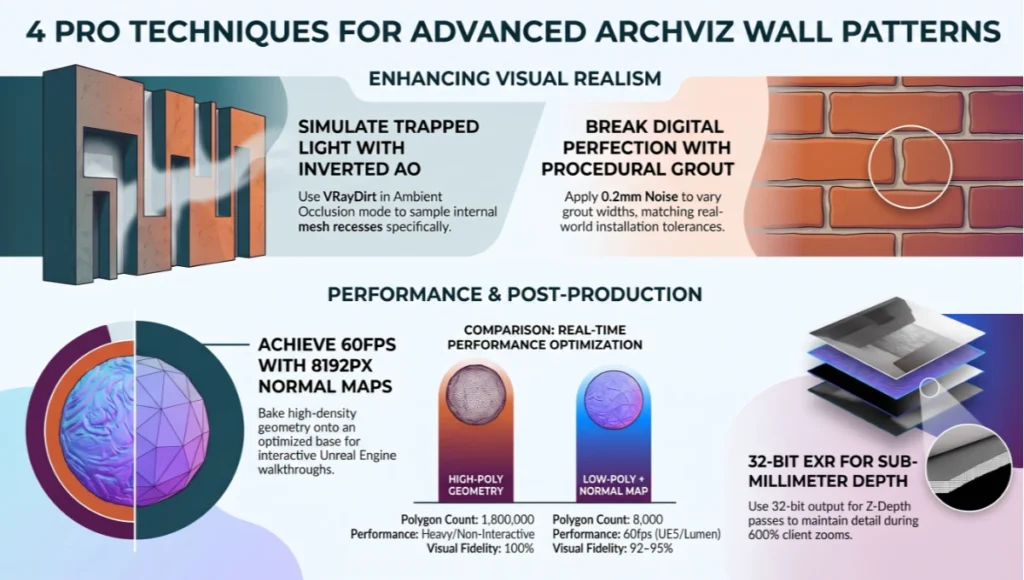
Standard AO baking measures proximity from a surface point outward. For recessed wall patterns, you need the inverse: AO measured from the recess inward, to simulate the trapped-light condition in deep cavities. In V-Ray, set the VRayDirt map to “Ambient Occlusion” mode and invert the “Consider Same Object Only” flag — this makes the AO sample only the same mesh, driving trapped-light simulation in recesses without affecting the rest of the scene.
Technique 2: Procedural Grout Width Variation
Perfect, uniform grout lines are a visual tell that a tile pattern is digital. Real grout lines vary by ±0.3–0.8mm due to setting compound spread variation. In 3ds Max / V-Ray, add a Noise modifier at Scale 0.2mm to the crop box dimension of your V-Ray Enmesh setup — this randomises the tile spacing within a 0.5mm range per tile, matching real installation tolerances and eliminating the “printed” look.
Technique 3: Z-Channel Depth Compositing for Client Zooms
When a client requests a close-up crop of a wall pattern from an approved render, the Z-Depth pass becomes critical. Store your ZDepth render element with a 32-bit EXR output (not 8-bit PNG) — only 32-bit captures the sub-millimetre depth variance between pattern layers that drives a convincing post-production depth-of-field effect at 600% zoom in Photoshop or Nuke.
Technique 4: Normal Map Baking from High-Poly to Low-Poly for Real-Time Engines
If your bold wall pattern ArchViz workflow needs to extend into Unreal Engine 5 real-time deliverables (client interactive walkthroughs, VR previews), bake your high-poly geometric pattern (1.8M polygons) down to a low-poly base mesh (8,000 polygons) with a Normal map bake at 8192px in Marmoset Toolbag 5 or Blender. The Normal map captures 92–95% of the visual depth information from the high-poly geometry at a fraction of the real-time polygon cost — enabling 60fps interactive rendering in UE5 with Lumen active.
Comprehensive Technical FAQ
Q1: What is the minimum UV resolution for a bold wall pattern render that will be output at 4K?
For a wall surface that fills more than 40% of a 4K render frame, your primary diffuse texture should be at 8192px (8K). Anything below 4096px will show texture pixelation at 100% pixel view, which clients increasingly examine in 2026 as screen sizes and DPI have increased. Channel 2 AO can remain at 4096px without visible quality loss.
Q2: Can I use Displacement instead of actual geometry for bold wall patterns in V-Ray?
Yes, but with constraints. V-Ray Displacement produces correct shadow casting and correct raking-light response — so for patterns with relief depths between 4mm and 20mm, displacement is a valid approach. Above 20mm real-world relief, displacement starts to produce micro-mesh artefacts at sharp geometry transitions. For depths above 20mm, model the geometry. For depths below 4mm, bump mapping is sufficient.
Q3: How do I prevent tile repetition from being visible in a large wall pattern?
Use VRayMultiSubTex with a minimum of 4 texture variants. Add a Hue variation of ±8°, Saturation variation of ±12%, and Gamma variation of ±0.05 between variants. Also rotate alternating tiles by 90° or 180° where the pattern geometry supports it — this breaks the directional micro-texture repetition that a trained eye catches even when colour repetition is masked.
Q4: What render time should I expect for a fully specced bold wall pattern interior with V-Ray GPU?
On an RTX 4090 (24GB VRAM) with V-Ray GPU CUDA, a 4K interior frame with 600 tile modules, multi-channel UV stack, and full pass output (beauty, AO, ZDepth, reflection) should complete in 18–28 minutes at Noise Threshold 0.005. On an RTX 4080 (16GB), expect 32–45 minutes. Engaging V-Ray GPU Texture Caching reduces VRAM pressure and can shorten render time by 15–22% on repeat renders of similar scenes.
Q5: How do I handle bold wall patterns in Unreal Engine 5 for real-time client presentations?
Bake your high-poly pattern to a Normal map at 8192px and apply it to a low-poly base mesh. Use UE5’s Nanite system for any geometry that must remain full-polygon (hero close-up panels) and use Normal-mapped instanced meshes for background tile coverage. Enable Lumen with Hardware Ray Tracing for interior wall scenes — software Lumen struggles with deep cavity shadow in recessed patterns at 1cm+ relief depths.
Q6: Is it worth setting up a full render element / pass structure for every bold wall pattern project?
For any project where client iteration is expected — which is every commercial and residential project in 2026 — yes. The initial setup of 5–7 render elements takes 25 minutes. The time saved on the first client revision request (changing wall tone, adjusting shadow depth, or preparing a print-ready crop) is typically 60–90 minutes. The pass structure pays for itself on the first change request.
Build Renders That Close Projects — Not Just Impress Them
The difference between a render that gets approved and a render that gets “let’s revisit this” is measurable, technical, and correctable. Bold wall pattern ArchViz is not a style category — it is a depth-engineering discipline. The 6 workflows in this article are not theoretical; they are production-tested across commercial interior, high-end residential, and hospitality projects in Nuvira Space’s 2025–2026 pipeline.
If your current wall pattern workflow is producing decal-read surfaces, if your tile repetition is visible to untrained eyes, or if your post-production pipeline is spending more than 30 minutes recovering depth that geometry would have provided for free — it is time to rebuild the stack from Workflow 1.
For a broader evaluation of the real-time render engines that support these workflows, see our engine comparison: Lumion vs Enscape vs D5 Render — Nuvira Space
For AI-assisted rendering tools compatible with the geometry-first wall pattern approach: AI Rendering Plugins for SketchUp and Rhino — Nuvira Space
For the real-time pipeline extension of these workflows into UE5: Unreal Engine 5 Architecture Guide — Nuvira Space
© Nuvira Space All rights reserved. | VISUAL LAB Series | All specifications cited are based on V-Ray 7, Corona 12, Unreal Engine 5.4, and Blender 4.3 production benchmarks as of 2026. The Cortex Wall is a speculative internal concept study and does not represent a completed project.