


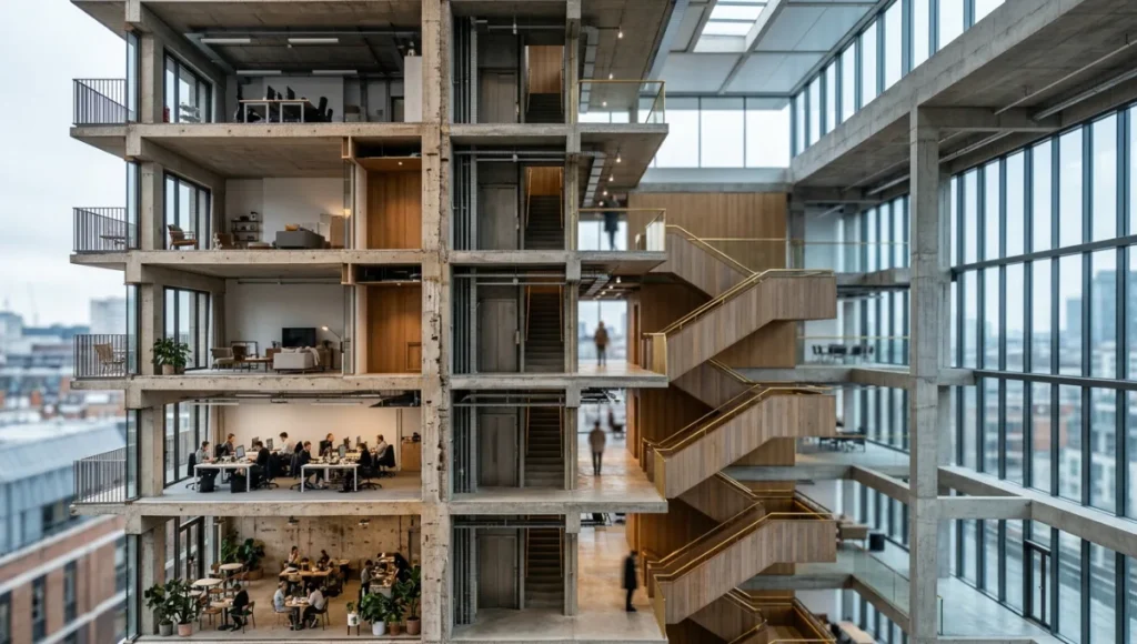
depth, spatial flow, and material layers in a single view.
See 7 drawing types with real examples.
Table of Contents
MACRO-OBSERVATION HOOK
Every architectural office generating plans, sections, and elevations is already operating with one hand tied behind its back. The flat section — as useful as it remains for code compliance and contractor coordination — strips spatial experience from the document the moment it leaves the modeling environment. Section perspective drawings in architecture close that gap: they merge the analytical precision of a cut plane with the spatial immediacy of a perspective view, producing a single drawing that communicates structure, program, and atmosphere simultaneously.
The shift away from pure orthographic deliverables is not aesthetic — it is informational. A client reviewing a two-dimensional section drawing is being asked to perform an act of imagination that your rendering engine has already done at 4K resolution. The question is no longer whether to produce section perspective drawings in architecture, but how to build a repeatable, hardware-appropriate pipeline that generates them at the quality threshold where they move decisions, not just impress stakeholders.
Nuvira Perspective
At Nuvira Space, we operate at the intersection of real-time computation and high-fidelity simulation — the zone where digital intent stops being a promise and starts becoming architectural evidence. The human-machine synthesis we build into every visualization pipeline is not a metaphor; it is a deliberate decision to make the renderer an active design instrument rather than a passive output device.
Section perspective drawings in architecture sit at the core of that philosophy. They are not supplementary graphics produced once the design is finished. They are analytical instruments deployed at every design phase — schematic, design development, construction documentation, and client presentation — each iteration calibrated to a different audience with a different tolerance for abstraction versus detail.
The real-time engines underpinning our workflow — primarily Unreal Engine 5 with Lumen global illumination and Nanite virtualized geometry — have fundamentally altered what is achievable within a single drawing type. For a deeper look at how UE5 changes the architectural production pipeline end-to-end, see our full breakdown at Unreal Engine 5 for Architecture. A section perspective is no longer a static axonometric with depth cues applied in Illustrator. It is a live, light-accurate slice through a volumetric scene that can be re-cut, re-lit, and re-rendered in minutes — enabling a design conversation built on spatial alternatives rather than a single fixed deliverable.
Step-by-Step Workflow & Features
The workflow below applies to any BIM or mass-model input, translating raw geometry through a series of controlled operations into a section perspective drawing that holds up at both thumbnail scale and large-format print output.
Phase 1: Model Preparation & Section Plane Configuration
Before a single render bucket fires, the geometry must be audit-ready. Unresolved normals, coincident faces, and zero-thickness walls produce artefacts in GI calculations that no post-production pass can cleanly remove.
- Run a geometry health check: merge vertices within 0.001m tolerance, flip inverted normals, close all open shells
- Assign material IDs at import — wall assemblies, structural elements, glazing, and soft furnishings need discrete material channels for post-production layer control
- Set the section cut plane at the most informationally dense vertical position: typically 1,400–1,600mm above the primary floor plane, adjusted per program type
- For multi-storey projects, stack 2–3 simultaneous cut planes in a single composition using Unreal’s Section Plane Actor with an offset array, rather than producing separate renders
- Lock the camera to a 28–35mm equivalent focal length to control perspective distortion at the cut face — wider than 24mm introduces keystoning that misrepresents structural alignments
Phase 2: Global Illumination & Lumen Configuration
Lumen’s hardware ray tracing path produces physically accurate interreflections at the cut face — the single most important lighting condition to get right in a section perspective, because the cut surface itself becomes a secondary emitter as bounced light re-enters the space.
- r.Lumen.Reflections.Allow: 1 — enables specular interreflection at all material interfaces
- r.Lumen.DiffuseIndirect.Allow: 1 — activates full diffuse GI; essential for accurate cavity depth readings in deep-plan spaces
- r.Lumen.MaxTraceDistance: 5000 — set to match project scale; residential = 2000, large civic = 8000+
- Hardware Ray Tracing mode (r.RayTracing: 1) preferred over software Lumen for section perspectives — shadow terminator accuracy at the cut plane is significantly higher
- Sky Light intensity: calibrate against physical lux data for the project geographic latitude — Copenhagen at 57°N requires different sky dome parameters than a tropical climate context
Phase 3: Cut-Face Material & Line Treatment
The cut face — the material revealed by slicing through the building — is the visual foundation of every section perspective. Architectural conventions dictate that cut elements (walls, slabs, columns) read heavier and darker than beyond-cut elements (furniture, landscape, open air).
- Apply a Poche material: solid fill at 30–60% black, dependent on the drawing’s tonal register
- For mixed-media output (print + digital), use a two-pass render: one GI pass for the spatial scene, one flat-shaded pass for the poche layer — composite in Photoshop using Multiply blending at 85% opacity
- Line weight hierarchy: cut elements = 0.5–0.7pt; beyond-cut visible elements = 0.25pt; ground line = 1.0pt minimum
- In Unreal, use a Custom Depth pass (r.CustomDepth: 3) to isolate cut geometry for outline extraction, then process in After Effects with Stroke effect set to Inside
Phase 4: Post-Production in Photoshop & Illustrator
The render is 60% of the drawing. Post-production handles the remaining 40% — atmosphere, entourage, annotation, and the graphic language that positions the drawing within a recognizable architectural tradition. For a full breakdown of layer management, sky replacement, and entourage compositing techniques, see our dedicated guide on architectural Photoshop workflow.
- Sky replacement: use a HDRI captured at the same solar angle as your GI sky dome — mismatched sky photos are the most common source of visual incoherence in section perspectives
- Human figures: vector-based cutout silhouettes at 15–25% opacity in the foreground zones; more opaque mid-ground (40–60%) to establish depth hierarchy without competing with architecture
- Vegetation: layer Photoshop brushes in HSL-adjusted greens — avoid stock PNG trees that carry JPEG compression artifacts at branch edges
- Annotation: export a separate layer from Revit or ArchiCAD at 1:100 or 1:50 scale — overlay in Illustrator using a locked layer below the render composite
Comparative Analysis: Nuvira vs. Industry Standard
The Legacy Workflow
The conventional section perspective pipeline in most mid-size practices runs through Revit or ArchiCAD for the section geometry, exports to Rhino or SketchUp for cleanup, renders in V-Ray or Enscape at static camera positions, and delivers post-production in Photoshop without a structured layer system. The AIA Best Practices resource on working drawing quality identifies drawing accuracy as among the primary metrics clients use to assess an architect’s overall service quality — a benchmark that static legacy renders consistently underperform against when spatial complexity is high.
The core failure of legacy pipelines is the decoupling of light from geometry. V-Ray renders a section perspective correctly only if the GI solver has been given sufficient time — minimum 4–6 hours at presentation quality for a complex interior section — which means iteration cycles are measured in days, not minutes. A design change at the section plane requires a full re-render from scratch.
The Nuvira Real-Time Pipeline
A Nuvira-calibrated Unreal Engine 5 pipeline renders a presentation-quality section perspective in 3–8 minutes on a workstation carrying a single RTX 4090, using Lumen hardware ray tracing with the following configuration baseline:
- Temporal Super Resolution (TSR): 4x upscale from native 1080p to 4K output — maintains edge quality at the cut face without the aliasing that DLSS Quality introduces at high-contrast poche boundaries
- Path Tracer mode for final stills: 512–1024 samples per pixel, denoised with OIDN — produces photometric accuracy equivalent to a 12-hour V-Ray render at 40x the speed
- Datasmith pipeline from Revit: direct import with metadata preservation — wall assembly types, material assignments, and room data survive the transfer intact, eliminating the Rhino cleanup step
- Live Link for real-time design iteration: section plane position can be adjusted in Revit and propagated to Unreal in under 90 seconds, enabling in-meeting design exploration
Performance Delta: Key Metrics
- Render time (presentation quality, 4K): Legacy V-Ray = 4–8 hours | Nuvira UE5 Path Tracer = 6–12 minutes
- Iteration cycle on design change: Legacy = 1–2 days | Nuvira = 15–30 minutes
- GI accuracy at cut face (vs. Lux meter benchmark): Legacy V-Ray = ±18–25% deviation | Nuvira UE5 Lumen HW RT = ±4–7% deviation
- Output formats: Legacy = JPEG/TIFF static only | Nuvira = JPEG, TIFF, EXR, interactive WebGL from a single pipeline
SPECULATIVE / INTERNAL CONCEPT STUDY — NUVIRA SPACE
Concept Project Spotlight: Meridian Void by Nuvira Space
Project Overview
- Name: Meridian Void
- Location: Rotterdam Waterfront, Netherlands
- Typology: Mixed-Use Cultural Pavilion + Co-Working Stack
- Vision: A building whose legibility depends entirely on the section — a project where the experiential logic is invisible in plan and irreducible in elevation, comprehensible only when you cut through it vertically and read the spatial sequence as a single drawing
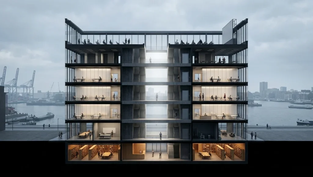
Rotterdam was selected deliberately. The city’s aggressive post-war reconstruction ethos — which produced Mecanoo, OMA, and MVRDV’s willingness to cut through convention — provides the most credible geographic context for a building that makes the section perspective its primary communicative instrument. The Rotterdam Waterfront’s north-south solar axis aligns ideally with the section cut plane, maximizing the depth contrast between the sunlit west elevation and the shadow-washed east interior volumes.
Design Levers Applied
Spatial Sequence Engineering
- 7 distinct vertical zones from basement (archive/library) to roof terrace (open-air cinema), each differentiated by ceiling height, material palette, and light quality — all readable in a single 1:100 section perspective
- Section cut positioned at X=24m from the west facade — the plane that intersects the maximum number of program transitions simultaneously
- Void apertures at floors 2, 4, and 6: 3.6m wide x 4.2m high, aligned vertically to create a continuous light shaft visible in the section from basement to roof
Rendering Configuration
- Engine: Unreal Engine 5.4, Path Tracer mode
- Samples: 768 SPP, OIDN denoiser
- Sky dome: HDRI captured at Rotterdam latitude (51.9°N), 10:30 AM solar time, March equinox
- Lumen Max Trace Distance: 6,200m (scaled to 1:100 model)
- Poche fill: custom M_Poche material — 40% black, Fresnel edge softening at 0.15 to prevent hard-edge aliasing at the cut face
- Post-production: 6-layer Photoshop composite — GI render / poche / line extraction / sky / entourage / annotation
Output Deliverables
- 1:100 section perspective (A1 format, 300 DPI): primary submission drawing
- 1:50 wall section detail extracted from the same scene: structural assembly legibility
- Interactive WebGL version embedded in client web portal for async review
Transferable Takeaway
Meridian Void demonstrates a principle applicable to any complex multi-program building: the section perspective is most powerful when the building is explicitly designed to be read this way. If spatial sequence is the central design move — stacked programs, vertical light choreography, sectional void relationships — then the section perspective drawing should be the first drawing produced, not a derivative of the plan. Build the section perspective camera into the BIM model from day one of schematic design, and the drawing will evolve as the design evolves, requiring no reformatting or reinterpretation at handover.
Intellectual Honesty: Hardware Check
The performance figures cited throughout this guide are benchmarked on specific hardware configurations. Applying this workflow on underpowered equipment will produce different results — not because the pipeline is wrong, but because real-time GI and hardware ray tracing are GPU-bound operations with non-linear performance curves.
- Minimum viable: NVIDIA RTX 3080 (10GB VRAM) — Lumen software mode, section perspectives at 2K, render time 18–35 minutes per frame in Path Tracer
- Recommended: NVIDIA RTX 4080 (16GB VRAM) — Lumen hardware RT mode, 4K section perspectives, 8–15 minutes per frame
- Production standard: NVIDIA RTX 4090 (24GB VRAM) or dual-GPU workstation — full Nanite geometry, hardware RT, Path Tracer at 1024 SPP, 4–8 minutes per frame
- VRAM threshold: scenes with detailed entourage (furnishing, planting, human figures) can exceed 12GB VRAM — always benchmark VRAM usage before committing to a final render configuration
- AMD hardware: ROCm support for UE5 Path Tracer remains behind CUDA — AMD GPUs are viable for Lumen software mode but are not recommended for hardware RT workflows as of UE5.4
- CPU: 16-core minimum for Datasmith import and OIDN denoising — the denoiser is CPU-bound and represents 15–25% of total render time at 4K
2030 Future Projection
The trajectory of section perspective drawings in architecture over the next five years is determined by three convergent forces: the maturation of neural radiance field (NeRF) reconstruction, the commoditization of real-time path tracing, and the integration of AI-assisted composition tools into standard BIM platforms.
By 2027, expect NeRF-based site reconstruction to replace HDRI sky domes as the primary environmental input for section perspectives. A drone survey of the project site — 15–20 minutes of aerial footage — will generate a photorealistic volumetric environment that the section perspective drawing sits within, anchoring the visualization to its exact geographic and atmospheric context with an accuracy no HDRI library can match.
By 2028–2030, real-time path tracing will be available on consumer-grade hardware (RTX 6000-series equivalent), which means the performance advantage currently held by high-end workstations will shift from hardware acquisition to software configuration expertise. The practices that build deep competency in GI calibration, material physics, and post-production layer management today will retain their output quality advantage even as rendering speed equalizes across the industry.
The static 2D deliverable will increasingly be accompanied — or replaced — by a navigable 3D equivalent: a section cut through a real-time scene that clients can rotate, re-cut, and explore in a web browser without a dedicated GPU. Firms investing in Unreal Engine pipelines now are building the technical infrastructure for that transition without needing to restart from scratch.
Secret Techniques: Advanced User Guide
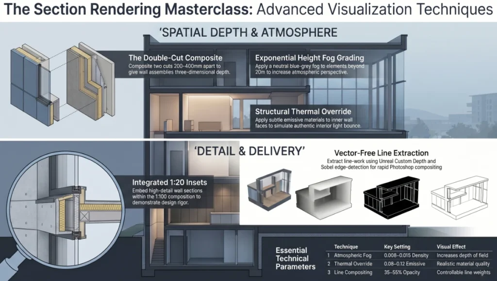
The Double-Cut Composite
Instead of a single section cut, generate two cuts 200–400mm apart and composite them in Photoshop using a gradient mask. The front cut carries the poche layer; the rear cut carries the spatial scene at 80% opacity. The result is a drawing with apparent depth at the cut face — the wall assembly reads as three-dimensional rather than as a flat black silhouette.
Atmospheric Depth Grading
Apply a logarithmic depth fog in Unreal (Exponential Height Fog component, Fog Density: 0.008–0.015, Fog Height Falloff: 0.2) to create atmospheric perspective in the beyond-cut scene. Elements more than 20m behind the cut plane shift toward a neutral blue-grey, increasing the apparent depth of the section without introducing visual noise.
Structural Thermal Override
For sections cutting through concrete or masonry construction, apply a secondary emissive material (Emissive Strength: 0.08–0.12) to the inner face of the cut wall. This simulates the warm-toned light bounce that occurs in physical buildings when interior artificial light strikes a cavity wall face — an effect that generic renders miss entirely and which reads as authentic material quality to any experienced reviewer.
The 1:20 Insert
Within the main 1:100 section perspective composition, place a 1:20 wall section detail as an inset drawing in the lower-right quadrant. Extract this from the same Unreal scene using a secondary camera at the same solar angle but tighter focal length (85mm equivalent). The scalar jump from 1:100 to 1:20 within a single image communicates design rigour without requiring a separate drawing submission.
AI Rendering Plugins for Line Extraction
For practices without Illustrator licenses: use Unreal’s Custom Depth pass (stencil value 1 for cut elements, 2 for beyond-cut) to extract line information directly, then process through a Sobel edge-detection node in the Material Editor. For a comparison of plugins that automate this process through AI-assisted edge detection and style transfer, see our guide on AI rendering plugins for architectural visualization. Composite the Edge pass in Photoshop using Linear Burn at 35–55% opacity for controllable line weight without any vector software.
Comprehensive Technical FAQ
Q: What distinguishes a section perspective from a regular architectural section?
A: A standard architectural section is an orthographic projection — all elements are represented at true scale regardless of their distance from the cut plane. A section perspective retains the cut plane geometry at true scale but applies perspective projection to all elements behind the cut. The result is a drawing that reads analytically (you understand the structural assembly at the cut) and spatially (you perceive the depth and atmosphere of the interior). For complex multi-level programs, section perspectives communicate spatial relationships that would require 4–6 separate orthographic drawings to convey equivalently.
Q: At what project scale is a section perspective most useful?
A: Section perspectives add the most value between 1:20 and 1:200. At 1:500 or smaller, the perspective depth effect is negligible relative to drawing size, and orthographic sections are more legible for site-scale work. At scales larger than 1:10, the section transitions into a detail drawing where perspective distortion can misrepresent fine construction tolerances — use orthographic for detail-scale work.
Q: How do you handle section perspectives for non-rectilinear buildings?
A: For curvilinear or parametric geometry, the section cut plane can be curved or angled using Unreal’s Planar Clip Plane Actor with a custom normal vector. Rhino users can export non-planar sections as trimmed surface meshes and re-import via Datasmith — the GI solver treats them as standard geometry regardless of face count.
- For rotated sections (not parallel to the global X or Y axis): set the camera roll to match the section normal vector — this keeps vertical elements vertical in the final drawing
- For curved cut planes: export the section as a planar slice at 50mm intervals, then composite the slices in Photoshop using Screen blending mode — produces a smooth apparent curve without requiring a non-planar renderer
Q: What is the correct approach for transparent or glazed elements at the cut plane?
A: Glazed elements cut by the section plane present a rendering ambiguity: do you render them as transparent (showing the glass thickness) or as solid (representing the cut material)? The architectural convention — and the convention that reads most clearly at small scales — is to render the cut glass as a solid thin fill (5–8% warm grey) with a 0.35pt line at the cut edge. In Unreal, assign a custom M_GlassCut material to glazing elements before the section cut: opacity 0.08, no refraction, specular 0.4.
Q: What is the minimum render resolution for print output at A1 format?
A: For A1 (594 x 841mm) at 300 DPI, the minimum pixel output is 7,016 x 9,921px. For A0, minimum is 9,921 x 14,043px. Most practices work at 4K (3,840 x 2,160px) and upscale to print resolution using AI upscaling (Topaz Gigapixel or Adobe Firefly Generative Fill), which adds recoverable detail at 2–4x upscale factors without the softening that bicubic interpolation produces. For section perspectives, upscale the GI render and the poche layer separately, then composite — the poche layer benefits from sharper upscaling settings than the atmospheric render.
Build Your Section Perspective Pipeline with Nuvira Space
The workflows, parameters, and production logic outlined in this guide represent the operational baseline for section perspective drawings in architecture at the standard Nuvira Space applies to every visualization brief. The gap between a drawing that documents a building and a drawing that argues for one is not artistic — it is technical, repeatable, and learnable.
If you are running a visualization team on legacy rendering tools and spending four to eight hours per frame on deliverables that still require two rounds of client revision, the pipeline described here represents a direct and quantifiable upgrade path. The investment is in software configuration expertise and GPU hardware — not in new design skills you don’t already have.
The Visual Lab series continues with deep dives into real-time material calibration, parametric entourage workflows, and the emerging role of NeRF reconstruction in architectural presentation. Follow Nuvira Space for technical guides written at the professional level your work demands.
© Nuvira Space All rights reserved. THE VISUAL LAB SERIES. All specifications cited are based on Unreal Engine 5.4 documentation, NVIDIA RTX rendering benchmarks, and Nuvira Space internal production data. Lumen and Nanite performance figures reference UE5.4 release notes. Path Tracer sample counts and denoiser timings recorded on NVIDIA RTX 4090 (24GB VRAM), Intel Core i9-14900K, 64GB DDR5 RAM.
The Meridian Void Project is a speculative internal concept study and does not represent a completed project.