

Table of Contents
The construction industry is still building the way it did in 1987. Manual sequencing, on-site tolerance guesswork, and a workforce model dependent on 454,000+ unfilled positions in the U.S. alone — these are not operational quirks. They are structural liabilities. Robotic construction tools for prefab workflows are not arriving to assist the existing system. They are arriving to replace its core logic.
At Nuvira Space, We Stopped Calling It “Automation”. Robotic Construction Tools Prefab.
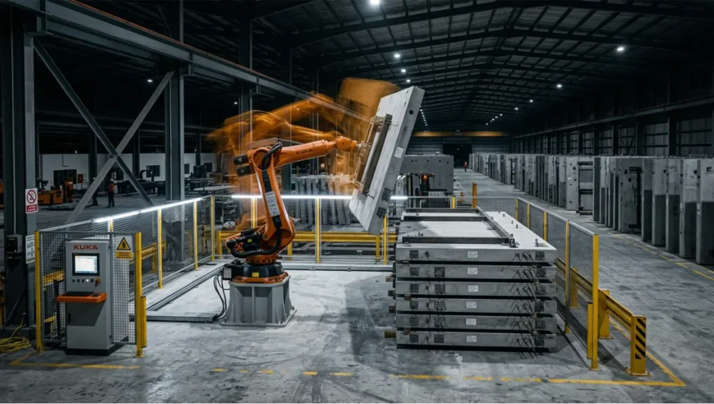
At Nuvira Space, we call it architectural recalibration. The moment a 6-axis robotic arm makes its first weld on a prefab panel with ±0.05 mm repeatability, the conversation shifts from “how do we build faster” to “how do we build smarter than the drawing allows.” Human-machine synthesis is not a feature you add to a project — it is the project. Every algorithm that governs a prefab robot’s motion envelope is, in effect, a design decision. And those decisions compound across a 10,000-unit housing pipeline in ways no human crew can match for consistency, speed, or structural accountability.
This is where Nuvira Space positions its authority: at the precise intersection of parametric thinking and physical fabrication. We do not review robotic tools as hardware. We evaluate them as architectural instruments — asking not what they can lift, but what they can build differently.
Technical Deep Dive: The 8 Structural Robotic Tools Redefining Prefab
1. KUKA KR QUANTEC Ultra — High-Payload Structural Assembly
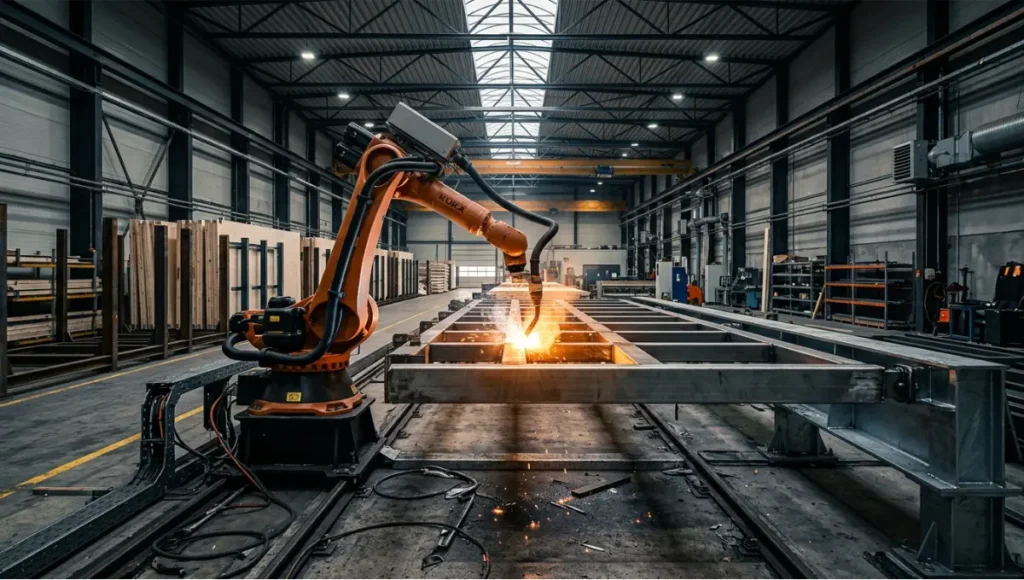
The KUKA KR QUANTEC Ultra is the workhorse of volumetric module assembly. Its operational specifications are not abstractions:
- Payload: 210–300 kg (configurable across series)
- Reach: 2,700 mm at maximum arm extension
- Repeatability: ±0.05 mm — critical for precast concrete panel alignment
- Axes: 6, with optional 7th external linear track
- Control system: KUKA KRC5 with SmartPAD Pro interface
So What? When you are assembling prefab bathroom pods that must stack 22 floors with cumulative tolerance under 3 mm, ±0.05 mm repeatability at the factory level is not impressive — it is the only viable option. Manual crews average ±3–5 mm per joint. The QUANTEC Ultra systematically removes that margin of error before the module ever leaves the factory floor.
Applications in Prefab:
- Structural steel and CLT panel alignment
- Volumetric module welding and bolting sequences
- Automated rebar cage assembly for precast concrete
2. FANUC R-2000iC — Multi-Task Heavy-Duty Arm
FANUC’s R-2000iC series handles the broadest payload range in active prefab deployment:
- Payload: 100–270 kg (model-dependent)
- Reach: 2,655 mm (270F variant)
- Repeatability: ±0.05 mm
- Axes: 6
- Cycle time advantage: 15–20% faster than comparable-payload KUKA variants in cut-and-weld sequences
So What? In a prefab steel-frame factory running 3 shifts, a 15% cycle time gain on beam fabrication translates directly to 1.5 additional floor assemblies per week per line. FANUC’s iRVision system — an integrated 2D/3D vision sensor — enables the arm to self-correct for material variance without halting production. That means a 12 mm warp in a delivered steel section does not stop the line.
Applications in Prefab:
- Steel frame cutting, welding, and inspection in single-cell workflows
- CLT beam routing with router end-of-arm tooling
- Panel lifting and placement in modular stack assembly
3. ABB IRB 6700 — Precision Finishing and MEP Integration
ABB’s IRB 6700 occupies a different position: finishing work and mechanical-electrical-plumbing (MEP) pre-routing, where precision outweighs payload.
- Payload: 150–300 kg (variant-dependent)
- Reach: 2,600–3,200 mm
- Repeatability: ±0.05 mm
- Software: ABB RobotStudio with OmniCore controller; built-in force-torque sensing
- Unique spec: Integrated collision avoidance reduces unplanned downtime by up to 36% in multi-robot cells
So What? MEP integration in prefab modules — pre-routing conduit, fitting plumbing risers, positioning HVAC ducting — requires tool-path accuracy that no human hand can maintain across 500 identical pods. The IRB 6700’s force-torque sensor allows it to detect a 0.3 N variance in pipe insertion resistance and self-adjust, preventing fitting cross-threading on plastic push-fit systems that would only show as a leak 6 months post-occupancy.
Applications in Prefab:
- MEP conduit routing and fitting in volumetric pods
- Window frame placement with force-feedback verification
- Surface finishing (sanding, sealing) on CLT panels
4. Promise Robotics — AI-Optimized Off-Site Platform (Factory-as-a-Service)
Promise Robotics operates on a fundamentally different commercial model: Factory-as-a-Service (FaaS). You do not buy the robot. You subscribe to fabrication output.
- Platform: AI-driven robotic arm cells pre-configured for wood-frame panel fabrication
- Output: Full wall panel, floor panel, or roof truss assembly in a single automated cell
- Speed: Panel cycle times reduced by up to 67% versus manual framing crews
- Digital intake: Takes builder’s architectural plans directly into the robotic motion planner — no manual G-code programming
- Business model: Per-panel pricing, eliminating CapEx barriers for mid-scale developers
So What? For a developer building 80-unit mid-rise timber-frame projects, Promise Robotics eliminates the $2.4M–$4.8M capital cost of establishing a private robotic prefab line. The FaaS model converts that expenditure into a predictable per-unit cost, scalable to demand. The AI motion planner also catches constructability conflicts — panel intersections, stud spacing anomalies — before fabrication begins, not during site assembly.
Applications in Prefab:
- Wood-frame panel fabrication for residential and light commercial
- Roof truss assembly with automated nail-plate placement
- Rapid-iteration prototype fabrication for design-build developers
5. Blueprint Robotics — Timber Frame Automation Cell
Blueprint Robotics (U.S.) and Randek (Sweden) represent the timber-specific end of the prefab robotics spectrum, where material behavior — wood’s anisotropic nature, moisture variability — demands specialized toolpath logic.
Blueprint Robotics specs:
- System type: Closed-loop robotic timber framing cell
- Precision: Sub-millimeter nail-plate positioning across panel runs
- Panel output: Wall panels, floor cassettes, and roof panels in a single integrated line
- Quality control: Automated vision inspection after every fastening sequence
Randek specs:
- System: Multi-station automated timber production line
- Output speed: Up to 300 m² of wall panel per shift
- Automation level: 90%+ of framing operations automated (cutting, nailing, insulation placement)
- Integration: BIM-to-machine direct file transfer via IFC or proprietary format
So What? At 300 m² per shift from a single Randek line, a 50-unit housing development’s entire wall panel inventory can be fabricated in under 3 working days. On a traditional site, that same scope requires 4–6 weeks of framing labor. The time delta is not a convenience — it is a financing advantage, compressing the period between land acquisition and revenue-generating occupancy.
6. Conjet Hydrodemolition Robot — Structural Preparation and Remediation
Prefab is not only new construction. Robotic construction tools for prefab increasingly include systems that prepare existing structures for modular retrofits — and Conjet’s hydrodemolition robots lead that category.
- Technology: High-pressure water jet at 500–2,500 bar operating pressure
- Application: Precise concrete surface removal for structural bonding in hybrid prefab-retrofit projects
- Dust/noise: Eliminates concrete dust (a known carcinogen under prolonged exposure) and reduces demolition noise by up to 40 dB versus mechanical chipping
- Accuracy: Programmed removal depth to ±1 mm — critical for rebar exposure in post-tensioned slab retrofits
So What? When a developer converts a 1970s concrete-frame office tower into residential units using prefab bathroom pods, the interface between existing slab and new volumetric module requires a prepared concrete surface with defined bond strength. Conjet’s hydrodemolition robots deliver that surface to specification without introducing microcrack networks from impact energy. The structural integrity of the hybrid assembly depends on it.
Applications:
- Slab preparation for prefab module interfaces in adaptive reuse projects (see also: adaptive reuse architecture examples)
- Precast panel surface activation for epoxy bonding
- Bridge and infrastructure prefab component remediation
7. Branch Technology — Cellular Fabrication (C-FAB) Robotic 3D Printing
Branch Technology’s Cellular Fabrication (C-FAB) process is the most architecturally specific robotic tool in this review — and the most structurally efficient per kilogram of material deposited.
- Process: Freeform 3D printing using a FANUC M-710iC/50 robotic arm with proprietary extrusion head
- Material: Carbon fiber-reinforced polymer matrix, printed in open lattice geometry
- Structural efficiency: Lattice structures achieve 60–80% material reduction versus solid cast equivalents at equivalent load-bearing performance
- Print volume: Up to 8 m × 4 m × 2.5 m in a single uninterrupted print run
- Application: Custom structural and façade panels for prefab cladding systems
So What? A conventionally cast concrete spandrel panel for a high-rise curtain wall system weighs approximately 850–1,200 kg per unit. A Branch Technology C-FAB structural panel engineered to the same load specification weighs 180–240 kg. At 40 panels per floor on a 30-floor tower, that is a structural dead load reduction of 25,200–36,000 kg per floor — compounding into foundation cost reductions that materially change the project’s structural engineering scope.
Applications in Prefab:
- Custom architectural façade panels (see also: digital twin building management)
- Structural core inserts for volumetric pods
- Formwork fabrication for complex precast geometries
8. Spot by Boston Dynamics — Autonomous Inspection and QA Integration
The 8th tool is not a fabrication arm. It is the quality assurance layer that validates everything the other 7 produce.
- Platform: Quadruped autonomous robot, 32 kg operating weight
- Payload capacity: 14 kg (sensor package)
- Sensor suite: LiDAR, thermal imaging, 360° visual inspection cameras, acoustic sensors
- Navigation: Simultaneous Localization and Mapping (SLAM) in GPS-denied factory environments
- Battery runtime: 90 minutes per charge; hot-swap capable for continuous deployment
- Data output: Point cloud scans accurate to ±2 mm for dimensional verification
So What? A prefab factory producing 200 wall panels per week cannot run manual dimensional QA on every unit at full line speed. Spot navigates the completed panel storage area autonomously, scans each unit against its BIM reference model, and flags any panel with a deviation exceeding 2 mm. That inspection loop — previously requiring 2 full-time QA technicians — runs continuously without fatigue, shift handover errors, or measurement instrument calibration drift.
Comparative Analysis: Robotic Prefab vs. Industry Standard
Solution: Robotic Construction Tools Prefab Workflow
| Metric | Robotic Prefab | Traditional On-Site Construction |
|---|---|---|
| Dimensional tolerance | ±0.05–2 mm | ±3–10 mm |
| Labor dependency | 30–50% reduction | 100% labor-dependent |
| Panel production speed | 300 m²/shift (timber) | 60–90 m²/shift (manual crew) |
| Waste generation | 5–8% material waste | 15–20% material waste |
| On-site accident exposure | Reduced by up to 40% (OSHA projection) | Standard exposure rates |
| Rework rate | 2–4% | 8–15% |
| Project timeline (80-unit block) | Compressed by 4–8 weeks | Full sequential timeline |
The Critical Gap: BIM-to-Machine Integration
The industry standard still treats design and fabrication as sequential handoffs — architect exports drawings, contractor interprets drawings, subcontractor executes. Each handoff introduces interpretation variance.
Robotic prefab collapses that chain. A BIM model in Revit or Archicad exports directly to a robotic motion planner (via IFC, direct API, or proprietary format like Promise Robotics’ intake system). The robot does not interpret the drawing — it executes the model. That distinction eliminates the most common category of prefab defects: dimensional errors introduced during human translation of design intent into fabrication instruction.
For deeper context on how generative design tools feed directly into fabrication-ready outputs, the integration logic parallels exactly what BIM-to-robot pipelines are now operationalizing.
Concept Project Spotlight
Speculative / Internal Concept Study — “The Meridian Stack” by Nuvira Space
Project Overview
Location: Singapore — Jurong Lake District (JLD), designated smart city precinct
Typology: Mixed-use residential tower, 32 floors, 280 units
Vision: A fully robotic prefab delivery pipeline for a high-density urban residential block, designed to operate within Singapore’s DfMA (Design for Manufacturing and Assembly) mandate while targeting a 40% productivity gain over the national housing baseline
Singapore is the correct geography for this concept. The Housing & Development Board (HDB) is deploying painting and plastering robots across approximately 50% of BTO (Build-To-Order) projects from 2025 onward, targeting a 40% overall productivity improvement by 2030. The national prefabricated construction market was valued at SGD 2.00 billion in 2024 and is projected to reach SGD 2.31 billion by 2029 — a market condition that makes robotic prefab economically rational, not experimental.
The Meridian Stack is designed to operate within and accelerate that policy environment.

Design Levers Applied
Fabrication System:
- Primary structural arm: KUKA KR QUANTEC Ultra on 18 m linear track, handling volumetric bathroom and kitchen pod assembly
- Timber panel line: Randek multi-station cell producing 300 m² of wall panel per shift
- Façade panel fabrication: Branch Technology C-FAB lattice panels, 40% lighter than precast equivalent
- Quality assurance: 2× Boston Dynamics Spot units running continuous SLAM-based dimensional inspection
Digital Backbone:
- BIM model (Revit 2026) exports to robotic motion planners via IFC 4.3 protocol
- Digital twin updated in real-time as panels are fabricated — live divergence tracking between design intent and physical output
- 0 manual G-code programming across all fabrication cells
Structural Metrics:
- Facade dead load reduction: 31,200 kg per floor versus conventional precast cladding
- Panel dimensional tolerance: ±0.8 mm at installation (combined fabrication + SLAM verification)
- On-site assembly crew: 14 workers for final installation (versus 62-person crew for equivalent conventional build)
- Projected timeline compression: 7.5 weeks versus comparable HDB BTO baseline
Spatial Outcome:
- Robotic pod fabrication enables bathroom pods with 2,350 mm floor-to-ceiling height (versus 2,100 mm standard in volumetric module systems where structural depth eats headroom)
- Panel tolerances tight enough to eliminate the 25 mm tolerance chase strip typically required at floor-to-wall interfaces — freeing 25 mm of livable depth around the full perimeter of each unit
Transferable Takeaway
You do not need to be building in Singapore to apply the Meridian Stack’s logic. The BIM-to-robot pipeline, the combination of heavy-payload arms for volumetric assembly and lighter specialist arms for MEP integration, and the autonomous QA layer — these are system-design decisions that translate to any prefab program at sufficient scale. The minimum viable scale where robotic prefab becomes cost-neutral versus manual fabrication is approximately 40–60 units. Above that threshold, the economics compound in favor of the robotic workflow on every subsequent unit.
Intellectual Honesty: Current Limitations
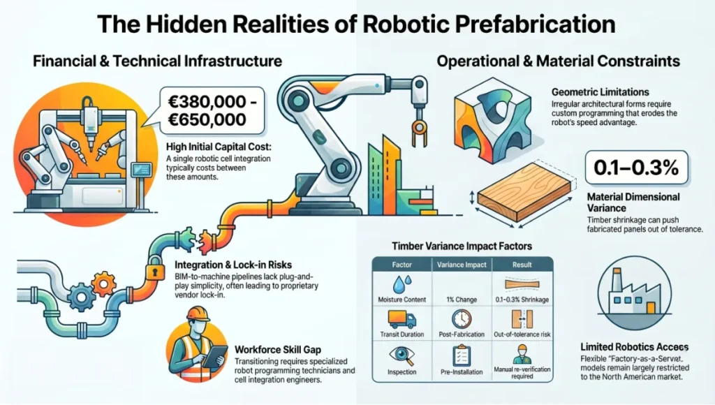
Robotic construction tools for prefab carry real constraints that no vendor datasheet will headline:
- Capital cost: A single KUKA KR QUANTEC Ultra cell with integration, tooling, and software runs €380,000–€650,000 before commissioning. FaaS models (Promise Robotics) mitigate this, but access remains limited to North American markets as of 2025.
- Geometry constraints: Robotic arms excel at repetitive, parametrically defined geometries. Highly irregular architectural forms — freeform curves, non-standard panel sizes — still require significant custom programming that erodes the speed advantage.
- Integration complexity: BIM-to-machine pipelines are not plug-and-play. IFC 4.3 protocol support is uneven across robot manufacturers, and proprietary formats create vendor lock-in risk.
- Workforce transition: Robotic cells require robot programming technicians and cell integration engineers — roles that do not yet have standardized training pipelines in most markets.
- Material variability: Timber’s moisture-driven dimensional variance (shrinkage of 0.1–0.3% per 1% moisture content change) can push fabricated panels outside tolerance in transit, requiring re-inspection before installation. Robots cannot fully account for post-fabrication material movement.
These are not arguments against robotic prefab. They are the specifications of the problem you are solving when you budget, plan, and staff a robotic prefab program correctly.
2030 Future Projection
By 2030, the architecture of robotic prefab will look materially different from 2025 in 4 specific dimensions:
- Multi-robot collaboration: Single-cell robotic fabrication will give way to 4–8 robot collaborative cells where arms hand off components to each other mid-sequence, eliminating the inter-station transport delays that currently account for 18–23% of total factory cycle time.
- AI-driven adaptive toolpaths: Current robotic motion planners execute pre-programmed paths. By 2030, on-machine AI will generate and update toolpaths in real-time based on sensor feedback, meaning a robot welding a slightly warped steel beam will adapt its weld path to the actual geometry — not the designed geometry — without halting production.
- On-site robotic deployment: Factory-only robotic prefab is the 2025 paradigm. By 2030, the distinction between “off-site” and “on-site” robotics will blur as mobile robotic platforms — mounted on tracked vehicles or elevated work platforms — perform installation tasks at height that currently require human crews.
- Material intelligence: Structural robotics will integrate embedded sensor networks (strain gauges, accelerometers) into prefab panels during fabrication — not as an add-on, but as a designed fabrication step. The building will be instrumented at birth, enabling real-time structural monitoring from day 1 of occupancy. For a deeper exploration of how sensor-embedded structures feed urban intelligence, see smart city sensors.
The global construction robotics market was valued at $168.2 million in 2022. Projections place it at $774.6 million by 2032. That trajectory is not a prediction — it is the current adoption curve, already in motion.
The Toolset: 5 Key Tools
Beyond the 8 structural robotic systems reviewed above, the software and integration layer that connects design to fabrication is where most prefab programs fail or succeed. These 5 tools define the digital backbone:
1. Autodesk Revit with Dynamo Scripting The industry standard BIM authoring environment. Dynamo enables parametric panel generation — designing a rule set, not individual panels — which feeds directly into robotic motion planners. Essential for programs above 30 units.
2. ABB RobotStudio Off-line robot programming and simulation environment. Allows complete cell simulation before physical commissioning, reducing cell setup time by 30–40%. Critical for multi-robot cell design and collision avoidance programming.
3. KUKA.Sim KUKA’s equivalent simulation environment. Most relevant for QUANTEC Ultra and KR FORTEC deployments in heavy structural assembly. Includes payload verification under dynamic motion conditions — the spec check that prevents wrist overload at production speed.
4. Rhino + Grasshopper + HAL Robotics The architect’s entry point into robotic fabrication. HAL Robotics translates Grasshopper geometry scripts directly into robotic toolpaths for KUKA, ABB, and FANUC arms. This is how architectural geometry becomes fabrication instruction without a manufacturing engineer in the loop. Directly relevant to robotic fabrication in architecture as explored in Nuvira’s earlier work.
5. Matterport Pro3 + BIM Integration Post-fabrication and post-installation spatial capture at 0.1% volumetric accuracy. Used for as-built vs. as-designed comparison, insurance documentation, and handover record. Increasingly integrated with Boston Dynamics Spot’s sensor payload for automated factory floor scanning.
Comprehensive Technical FAQ
Q: What is the minimum project scale where robotic construction tools for prefab become cost-viable?
A: The cost-neutrality threshold varies by system type:
- Timber panel robotics (Randek, Blueprint): Approximately 40–60 units of equivalent panel geometry
- Volumetric pod assembly (KUKA, ABB heavy arms): Approximately 80–120 pods per program
- FaaS model (Promise Robotics): Cost-positive from first panel; no CapEx threshold
Below these thresholds, manual fabrication retains a cost advantage. Above them, the per-unit cost curves cross and every additional unit compounds the robotic workflow’s advantage.
Q: Can robotic prefab tools handle irregular or architecturally complex geometries?
A: With conditions. Standard 6-axis arms handle linear, planar, and simple curved geometries efficiently. Complex freeform geometry — parametric facade panels, non-standard angles — requires:
- Custom end-of-arm tooling
- Extended off-line programming time (2–6 weeks per novel geometry)
- Tolerance verification at each unique panel type
Branch Technology’s C-FAB process is the exception: its freeform 3D printing workflow handles non-repeating geometries natively, as each panel is printed rather than machined. This makes it the appropriate tool for architecturally unique cladding systems where repetition cannot be assumed.
Q: How does BIM-to-robot file transfer actually work in a production environment?
A: The dominant pipeline as of 2025:
- IFC 4.3 export from Revit or Archicad → imported into ABB RobotStudio, KUKA.Sim, or HAL Robotics
- Direct API integration (Promise Robotics’ proprietary intake system) — architectural plans enter, motion plans exit, no intermediate format
- Grasshopper → HAL Robotics for geometry-first workflows where the architectural form drives the toolpath
The critical constraint: not all robotic controllers read IFC natively. Most require an intermediate conversion to manufacturer-specific robot language (RAPID for ABB, KRL for KUKA, Karel for FANUC). This translation step is where integration engineers earn their fee.
Q: What safety standards govern robotic prefab facilities?
A: The applicable standards framework:
- ISO 10218-1 and 10218-2: Industrial robot safety — robot design and integration requirements
- ISO/TS 15066: Collaborative robot operation (applicable where Spot or other mobile robots operate alongside humans)
- OSHA 1910.217: Machine guarding requirements for U.S. facilities
- CE Marking (EU): Required for robotic cells deployed in European prefab facilities
Most prefab facilities operate with physical guarding (safety fencing, light curtains) around heavy-payload arms. Collaborative robot standards (ISO/TS 15066) apply specifically to force-limited cobots and autonomous mobile platforms like Spot that operate in shared human-robot spaces.
Q: How do robotic construction tools interact with modular vs. prefab delivery methods?
A: The distinction matters:
- Prefab: Individual components (panels, beams, pods) fabricated off-site, assembled on-site
- Modular: Entire volumetric room modules fabricated off-site, stacked and connected on-site
Robotic tools apply differently:
- Prefab panel fabrication: Randek, Blueprint Robotics, KUKA on linear tracks
- Volumetric module assembly: KUKA KR QUANTEC Ultra, ABB IRB 6700 for MEP integration within the module
- Modular stack installation: Currently limited robotic deployment; crane + human crew remains standard for the final stack-and-connect operation
For a full comparison of how these delivery methods differ structurally and commercially, the modular vs. prefab homes breakdown provides the foundational framing.
Q: What does the AIA say about robotic fabrication in practice?
A: The American Institute of Architects (AIA) has documented robotic fabrication through its Technology in Architectural Practice (TAP) knowledge community and case study publications. AIA case studies — particularly those covering robotic timber fabrication and prefab panel systems in educational and healthcare typologies — consistently report that BIM-to-fabrication integration is the primary productivity driver, not robot speed alone. The AIA’s findings align with the Nuvira position: the machine executes; the value is in the data pipeline that instructs it.
Your Fabrication Line Is a Design Decision
The 8 robotic construction tools in this review are not products to be evaluated in isolation. They are design instruments — each one encoding a set of assumptions about geometry, material, tolerance, and delivery speed that will propagate through every unit your program produces.
Before you specify a panel system, before you negotiate a prefab subcontract, before you finalize a module layout — you need to know which robotic tools your fabricator is actually running, at what specification, and how that specification connects back to your BIM model.
If you are building more than 40 units, you are already in robotic prefab territory, whether you have made that decision consciously or not. The fabricator you select will make it for you.
The specification starts with the 3D printed neighborhoods paradigm and runs all the way through to the structural precision of the robot welding your volumetric pod. Nuvira Space maps that entire chain — from design intent to fabricated reality.
Get the data. Make the specification yours.
© Nuvira Space — All rights reserved. | Future Tech Series | All specifications cited are based on manufacturer published datasheets (KUKA, FANUC, ABB, Boston Dynamics), industry market research (ResearchAndMarkets.com Singapore Prefabricated Construction Databook Q4 2025), and publicly available robotics performance benchmarks as of Q1 2026. The Meridian Stack is a speculative internal concept study and does not represent a completed project.