

Table of Contents
Real time ray tracing architecture speed quality is no longer a tradeoff you negotiate once at the start of a project and forget about. It is a live variable that shifts every time you adjust a light rig, swap a material, or push a camera through a glazed atrium, and the studios still treating it as a fixed setting from 2021 are the ones burning unpaid hours waiting on frames they could be reviewing in real time.
Nuvira Perspective
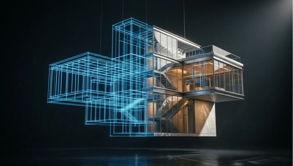
At Nuvira Space, we treat the render viewport as a design instrument, not a deliverable factory. The conversation about real time ray tracing architecture speed quality usually gets framed as a hardware question — more CUDA cores, more VRAM, faster denoisers. That framing misses the actual shift. What changed is the latency between a design decision and photorealistic feedback. When that gap collapses from ninety minutes to under a second, you stop designing for the render and start designing inside it.
This is the bridge between digital intent and architectural reality that real-time engines and high-fidelity simulation now make possible. A massing study, a material swap, a sun-angle check at 4pm in December — these used to be batch jobs you queued and walked away from. Now they are conversations you have with the model while a client is still in the room. That is the operational core of what we mean when we talk about human-machine synthesis: the machine stops being a renderer you wait on and becomes a collaborator you think alongside.
The rest of this guide breaks down how that synthesis actually works at the parameter level — global illumination settings, denoising architecture, hardware ceilings, and the workflow restructuring required to use real-time ray tracing as a primary design tool rather than a marketing gimmick bolted onto the end of a project. It sits alongside our broader coverage of how NeRF-based capture is reshaping architectural visualization, since both techniques are pushing the same industry away from batch rendering and toward continuous, explorable digital representations of physical space.
Step-by-Step Workflow & Features
Stage 1: Scene Preparation for Real-Time Path Tracing
Real-time ray tracing engines are forgiving about polycount in ways offline renderers never were, but they are unforgiving about scene hygiene. If you are still deciding which engine to standardize on, our comparison of Lumion, Enscape, and D5 Render covers the tradeoffs in more depth than fits here. Before you load a scene into a real-time path tracer, run these checks:
- Collapse instanced geometry where the engine’s BVH builder will otherwise duplicate acceleration structures unnecessarily
- Flag emissive materials explicitly — engines like Chaos Vantage and Unreal Engine’s Lumen treat self-illuminating surfaces as light sources that affect bounce calculations, and unflagged emissives silently break GI
- Strip unused UV channels above UV0 unless you are driving decals or lightmap baking, since they add memory overhead with zero real-time payoff
- Verify normal direction on glazing and water planes, because inverted normals on refractive surfaces are the single most common cause of black-screen artifacts in real-time path tracing
Stage 2: Global Illumination Calibration
Global illumination is where real time ray tracing architecture speed quality is decided, because GI is the single most expensive calculation in the pipeline and the one most visible to a client’s eye.
Bounce Limit Strategy
Most real-time path tracers default to two or three diffuse bounces. For interior daylight studies — the bread-and-butter request for any visualization studio — two bounces is usually insufficient; light pooling under furniture and color bleed from saturated upholstery only resolves correctly at three to four bounces. Push beyond four and you are spending frame budget on light contribution that is statistically invisible.
Sample Accumulation Over Time
- Static camera, hero still: let temporal accumulation run 200–400 frames before capture — this is the technique that lets real-time engines reach offline-renderer noise floors
- Walkthrough animation: accumulation resets every frame, so noise floor is fixed by per-frame sample count, typically 4–16 samples depending on GPU class
- VR / live client session: prioritize frame stability over noise floor — a slightly noisier image at a locked 90fps beats a cleaner image with frame drops, because frame drops break presence
Stage 3: Denoising Pipeline Architecture
Denoising is not a single step — it is a pipeline with its own ordering logic. Spatial denoisers (like NVIDIA’s OptiX AI-Accelerated Denoiser) clean individual frames but smear fine detail like foliage and fabric weave. Temporal denoisers reuse information across frames, which is why a walkthrough looks cleaner than a single extracted frame from that same walkthrough.
- Run spatial denoising first on the raw path-traced output to remove high-frequency noise
- Apply temporal accumulation second, feeding the denoised frame back as history for the next frame
- Reserve a sharpening pass for final delivery only — applying it earlier in the chain amplifies denoiser artifacts instead of image detail
Stage 4: Material and Lighting Calibration for Speed
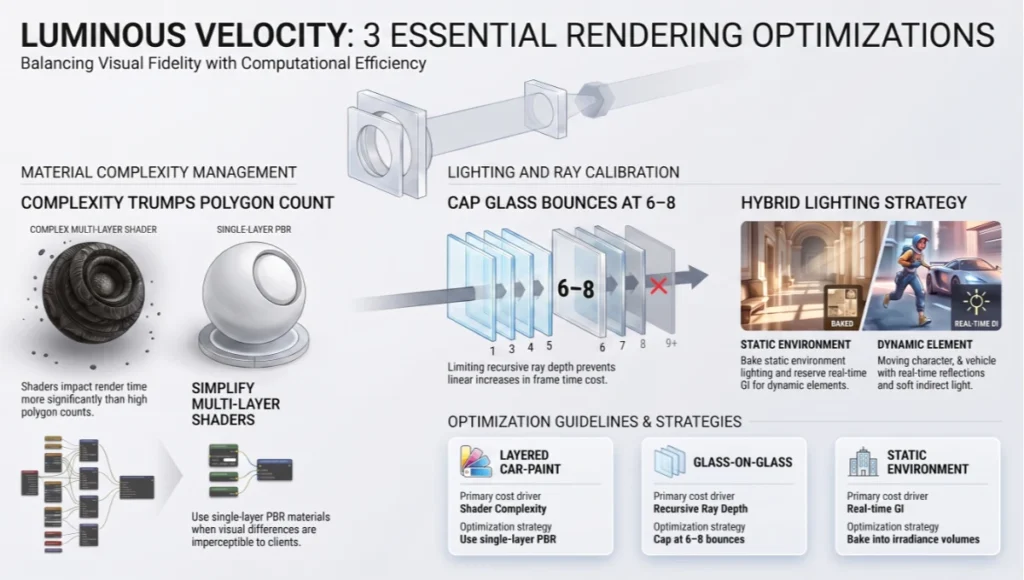
Ray-traced reflections and refractions scale in cost with material complexity, not polygon count. A single layered car-paint shader with clear-coat, base coat, and metallic flake can cost more render time than an entire glazing facade using a simple physically-based glass shader.
- Use single-layer PBR materials wherever the visual difference from multi-layer shaders is below client-perceptible threshold
- Cap recursive ray depth for glass-on-glass conditions (atria, curtain walls) at 6–8 bounces; beyond that, returns are negligible and frame time cost is linear
- Bake static environment lighting (skylight, distant sun) into irradiance volumes where the engine supports it, reserving full real-time GI calculation for dynamic elements only
Comparative Analysis: Nuvira Vs. Industry Standard
The industry-standard pipeline for most mid-size architectural visualization studios still routes hero stills through an offline batch renderer — V-Ray, Corona, or Arnold — while using real-time engines only for client-facing walkthroughs. Nuvira’s pipeline inverts that priority.
Render Time Allocation
- Industry standard: roughly 60–70% of total project render-hours spent on offline batch queues for stills, with real-time reserved for secondary deliverables
- Nuvira approach: real-time path tracing handles primary design iteration and client review; offline rendering is reserved only for final marketing-grade stills requiring sub-pixel-perfect anti-aliasing
Iteration Depth Per Design Phase
- Industry standard: 3–5 lighting iterations per design phase, constrained by render queue turnaround
- Nuvira approach: 15–30 lighting iterations per design phase, because each iteration costs seconds rather than tens of minutes
Client Review Format
- Industry standard: pre-rendered video walkthrough, locked camera path, no live adjustment during the client call
- Nuvira approach: live-linked real-time session where camera, lighting, and material decisions are made and seen during the call itself
Concept Project Spotlight
Speculative / Internal Concept Study — “Tidal Threshold” by Nuvira Space
Project Overview (Location / Typology / Vision)
Tidal Threshold is an internal concept study set in Rotterdam, a city whose relationship with water — storm-surge barriers, floating architecture pilots, and a waterfront that floods by design rather than accident — made it a useful real-world testbed for the lighting conditions we wanted to stress-test. The typology is a mixed-use cultural pavilion at the harbor edge, conceived around a folded glazed roof that admits low-angle northern light across a double-height exhibition floor.
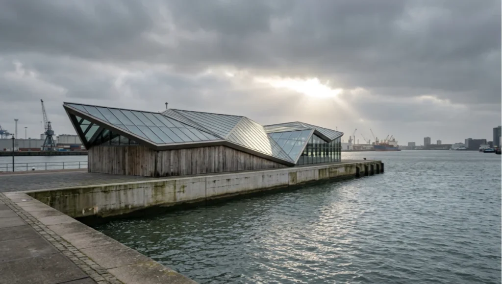
The vision was never to design a building for Rotterdam specifically — it was to use Rotterdam’s documented light data, water reflectivity, and overcast frequency as ground-truth conditions for testing whether our real-time GI calibration holds up against a genuinely difficult lighting environment, rather than the high-contrast sun studies most demo scenes are built around.
Design Levers Applied
Lighting Conditions Modeled
- Diffuse overcast sky model calibrated against Rotterdam’s average annual cloud cover, which sits well above 60% — a deliberately unforgiving condition for GI bounce accuracy
- Low-angle winter sun (10–15 degrees) raking across the harbor water plane, testing ray-traced reflection accuracy on a moving, refractive surface rather than a static glass facade
- Interior light pooling from a folded roof geometry with eleven distinct facet angles, each contributing a different bounce path into the exhibition floor
Technical Parameters
- Four-bounce GI ceiling, validated against the color-bleed test described in Stage 2 above
- Temporal accumulation locked to 320 frames for the three hero stills produced from this study
- Single-layer PBR glass on the roof glazing, multi-layer reserved only for the harbor-facing curtain wall where client-facing renders justified the added cost
Transferable Takeaway
The lesson from Tidal Threshold was not about Rotterdam specifically — it was that GI calibration tuned against best-case sun studies fails quietly under sustained overcast conditions. Any studio whose default test scenes are sunny days with hard shadows should run at least one overcast, low-angle-light stress test before trusting a GI bounce-count setting across an entire project pipeline.
Intellectual Honesty: Hardware Check
Real time ray tracing architecture speed quality claims you see in marketing material almost always assume a top-tier GPU and a controlled demo scene. Be honest with your studio about what your actual hardware delivers.
- Consumer RTX 4070/4080-class cards: comfortable real-time path tracing for interior residential scale scenes; struggle to hold frame rate on large exterior masterplans with dense vegetation
- RTX 4090 / professional RTX 6000 Ada: handles most single-building exterior and interior combinations at production quality; large urban-scale scenes still require LOD discipline
- Multi-GPU or cloud rendering rigs: necessary for anything approaching city-block scale in real time, and the cost-per-hour math needs to be run against your actual project margins, not against the demo reel
If your studio’s hardware sits below the RTX 4070 tier, real-time path tracing for client-facing work is not yet a realistic substitute for a well-optimized rasterized pipeline with baked lighting. For a deeper hardware-tier breakdown, see our guide to the best GPUs for rendering in 2026. Acknowledge that constraint before promising clients a capability your machines cannot sustain. Industry bodies like the AIA’s Technology in Architectural Practice Knowledge Community track exactly this kind of workflow shift across member firms, and their case material is a useful sanity check against vendor marketing claims.
2030 Future Projection
Extrapolating from the hardware trajectory of the last three GPU generations, native 4K real-time path tracing at sustained frame rates without upscaling assistance is a reasonable expectation by 2029–2030. That shift will not just speed up current workflows — it will eliminate the category distinction between “real-time preview” and “final render” entirely, since the preview and the deliverable will be the same calculation at the same fidelity.
The more disruptive shift is in collaborative format. Multi-user real-time sessions, where an architect, a client, and a contractor occupy the same rendered space simultaneously and make live geometry or material changes, are already functional in early-access tools. By 2030, this is likely to be the default client presentation format for any project above a moderate scale, displacing the pre-rendered walkthrough video almost entirely.
Secret Techniques: Advanced User Guide
- Light-linking isolation: disable GI contribution from background or context geometry that will not appear in the final crop, recovering frame budget without visible quality loss
- Proxy swap on approach: keep simplified proxy geometry loaded for distant context buildings and swap to full-detail only within camera-relevant range, scripted via a distance trigger rather than manual LOD switching
- Denoiser pre-warming: run a low-sample pass purely to populate temporal history buffers before the client-facing session begins, so the first frames the client sees are not the noisiest ones
- Material LOD by camera distance: swap multi-layer shaders for single-layer equivalents automatically past a defined camera distance, since layered detail is imperceptible beyond a few meters anyway
Comprehensive Technical FAQ
Core Concepts
Q: Does real-time ray tracing fully replace offline rendering for architectural visualization?
A: Not yet, for final marketing-grade stills requiring the highest possible anti-aliasing and sub-pixel detail. It does replace offline rendering for the iterative design and client-review stages, which is where most studio hours were historically lost.
Q: What GI bounce count should I default to for interior scenes?
A: Three to four diffuse bounces is the practical default for most interior daylight studies. Below three, color bleed and light pooling under furniture resolve incorrectly; above four, the added render cost rarely produces a perceptible improvement.
Hardware and Performance
Q: What is the minimum GPU tier for production-quality real-time path tracing?
A: An RTX 4070-class card is the realistic floor for interior residential-scale scenes. Larger exterior or urban-scale work benefits substantially from RTX 4090 or professional RTX 6000 Ada-class hardware.
Q: Why does my real-time scene flicker or show black artifacts on glass?
A: Inverted normals on refractive surfaces are the most common cause. Check glazing and water plane normal direction before adjusting any GI or denoiser settings.
- Spatial denoising cleans single frames but smears fine detail
- Temporal denoising reuses cross-frame data and is why animations look cleaner than extracted stills
- Sharpening should always be the final step in the chain, never applied before denoising
Talk to the Visual Lab About Your Pipeline
If your studio is still routing every client revision through an overnight render queue, the workflow restructuring described in this guide is worth a direct conversation. Nuvira Space’s Visual Lab works with architecture and visualization teams who want to move design review into real time rather than around it — bring a scene, and we will show you where your current pipeline is losing hours.
© Nuvira Space. All rights reserved. | THE VISUAL LAB Series | All specifications cited are based on internal pipeline testing and publicly available engine documentation, no external links implied. The Tidal Threshold study is a speculative internal concept study and does not represent a completed project.