


structural precision. See 7 data-driven stages architects use today.
Table of Contents
The parametric architecture design process is not an upgrade to conventional design—it is a replacement. Traditional workflows route a project through serial handoffs: sketch to CAD, CAD to structural, structural to fabrication. Each transfer introduces lag, version drift, and interpretation error. A floor-plan revision that takes 3 seconds to type into a Grasshopper parameter slider takes 4.7 days on average in a conventional drawing-revision cycle. That delta, compounded across a 400-iteration design phase, is where projects lose 18–32% of their scheduled time before a single column is poured.
The buildings reshaping skylines in Singapore, Shenzhen, and Rotterdam did not emerge from a drafting table. They emerged from a relational model—one in which geometry, structure, climate performance, and fabrication tolerances are simultaneous inputs, not sequential deliverables. The parametric architecture design process governs that simultaneity. This article breaks it into 5 precise, operational phases—each with the toolchains, metrics, and decision gates that convert algorithmic intent into physical space.
Nuvira Perspective, the Algorithm Is the Architect
At Nuvira Space, we treat the parametric stack not as a visualization assist but as the primary design intelligence. The architect’s role has shifted from form-maker to system-designer—a person who programs constraints, calibrates fitness criteria, and interprets what the model produces. That is not a diminishment of creativity; it is the highest form of it. You are no longer drawing a building. You are authoring the logic that generates thousands of buildings and selecting the 1 that meets every constraint simultaneously.
This is human-machine synthesis in its most productive expression. The machine handles the 1,000-variable optimization across 600 facade panels. You handle the question of what the 27th-floor occupant feels when morning light refracts at 14° through a perforated titanium skin. Both decisions belong to the same workflow. This piece is an operational brief for that workflow.
The Parametric Architecture Design Process: 5 Precise Phases
The 5 phases below are not theoretical stages. They represent the actual sequence of decision gates used in contemporary parametric practice. Skipping or compressing any phase produces model instability downstream—typically discovered at fabrication, which is the worst possible moment.
Phase 1 — Parameter Definition and Constraint Mapping
The parametric process does not begin with form. It begins with constraint. Phase 1 is the translation of a design brief into a structured variable set—the formal act of converting client requirements, site data, and regulatory limits into Grasshopper sliders, Dynamo nodes, or Python-scripted inputs that the model can compute against.
What Gets Defined in Phase 1
- Site envelope: Setback distances (e.g., 4.5 m minimum street setback, 2.2 m side), FAR limits, shadow-cone restrictions from adjacent structures
- Performance targets: Energy Use Intensity ceiling (e.g., ≤75 kWh/m²/year), daylighting threshold (Spatial Daylight Autonomy ≥50% of occupied area at 300 lux), structural drift limit (H/500 under wind load)
- Material parameters: Panel dimensions, weight limits per anchor point, thermal expansion coefficients, minimum bend radius for cold-formed steel
- Fabrication tolerances: ±0.4 mm CNC routing tolerance, ±2.0 mm on-site assembly tolerance, maximum panel weight of 38 kg for single-person installation
The output of Phase 1 is not a sketch. It is a structured parameter file—a JSON or GH data tree that becomes the immutable spine of every subsequent phase. If Phase 1 is vague, the model will generate solutions that are technically valid but architecturally incoherent. Precision here is non-negotiable.
Phase 2 — Algorithmic Geometry Generation and Environmental Simulation
Phase 2 is where the parameter set becomes 3-dimensional geometry—and simultaneously, where that geometry is tested against real-world environmental conditions. The defining characteristic of parametric practice is that these 2 operations happen in parallel, not in sequence.
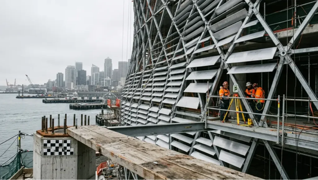
Parametric architecture design process in progress — CNC-pressed aluminium louvre panels being installed on a diagrid steel exoskeleton facade at a waterfront construction site, photographed with 24mm tilt-shift lens under diffused morning light, showing unique panel angle variation and robotic total station survey equipment
Geometry Engine Specifications
- Primary platform: Rhinoceros 3D 8.x with Grasshopper 1.0.0007 for visual scripting
- Structural feedback: Karamba3D 2.2.0 running finite element analysis (FEA) inline—beam-column stress mapped to colour gradient, live, on each geometry change
- Climate simulation: Ladybug Tools 1.8.0 with EnergyPlus 24.1.0 engine; processes solar irradiance data (TMY3 files), wind rose, and EUI projection in ≤12-minute simulation cycles
- Iteration velocity: 400–1,200 geometry variants generated per working session under typical parameter sweep conditions
Singapore’s Jewel Changi Airport—a 135,700 m² toroidal structure housing 280 retail units and a 40-metre indoor waterfall—was developed using a parametric geometry workflow that simultaneously resolved the structural ring beam geometry, the ETFE cushion pattern across 9,000+ panels, and solar gain through the glass dome. The simultaneity of that resolution is what made the project constructible on a 4-year schedule. A sequential workflow would have required 3–4 additional years of back-and-forth between the structural, envelope, and environmental teams.
| INFORMATION GAIN Phase 2 collapses what was once a 3-stage sequential process (concept geometry → structural check → environmental simulation) into a single real-time feedback loop. The performance gap between this and conventional workflows compounds across every design iteration. |
Phase 3 — Structural and Fabrication Optimization
Phase 3 is the discipline interface: where the architect’s geometric intent meets the structural engineer’s load path and the fabricator’s toolpath. In a conventional workflow, these 3 parties operate from 2D drawings passed over email. In the parametric workflow, they share a single live model. The difference is not organizational—it is mathematical.
Structural Optimization Variables
- Cross-section size and material grade for each structural member (driven by Karamba3D utilization ratio output, target ≤90% utilization)
- Column grid spacing optimization—typically tested across 15–40 grid configurations before a least-weight solution is selected
- Slab thickness variation by bay (parametric thinning where span-to-depth ratios permit, typically 1:28 for two-way flat slabs)
- Connection geometry—generated by script, CNC-ready, with ±0.4 mm tolerance baked into the output file
Fabrication Data Outputs from Phase 3
- CNC routing files: DXF nested layouts for flat-cut components; SVG paths for waterjet
- Robotic toolpaths: KUKA.PRC scripts for 8-axis robotic arm milling, wire bending, or concrete formwork carving
- Assembly sequencing: Exploded-view animations generated parametrically from the model, keyed to installation sequence for on-site QC
- BOM generation: Automated Bill of Materials with panel ID, material, weight, anchor type, and grid coordinate—linked live to the model
The key phrase is “linked live.” When a column shifts 300 mm in Phase 3 to resolve a beam utilization conflict, the facade panel layout, the BOM, the CNC files, and the assembly sequence update automatically. In a traditional workflow, that column shift triggers a multi-week revision cascade across 8–12 separate drawing packages.
Phase 4 — BIM Integration and Documentation
Phase 4 is the handoff from parametric model to construction documentation—but in the parametric process, “handoff” is a misnomer. The parametric model does not get converted into Revit; it drives Revit through a live link. Dynamo scripts translate Grasshopper geometry into native Revit families, maintaining the relational logic of the original model.
BIM Integration Specifications
- Level of Development: LOD 350 for structural and envelope elements by Phase 4 completion (sufficient for permit submission and contractor pricing)
- IFC export: IFC 4.x schema, validated against BIMcollab Nexus clash detection; clash tolerance set at 25 mm for MEP/structure coordination
- Drawing generation: Automated plan, section, and elevation extraction from the Revit model; revision-controlled by Grasshopper parameter version number
- Quantity takeoff: Revit Schedule linked to parametric model; concrete volume, rebar weight, and glazing area update per parameter change
Rotterdam’s Markthal—a 228-metre arch enclosing 228 apartments above a 100-stall indoor market—exemplifies this integration. MVRDV’s team used a parametric BIM workflow to coordinate the arch’s structural steel, the 11,000 m² artwork-clad ceiling, and the residential units’ internal layouts simultaneously. The result: a project that resolved 3 programs (retail, residential, public space) in a structural form with zero standard components.
Phase 5 — Fabrication Output and Construction Feedback
Phase 5 closes the loop. Construction feedback—as-built survey data, laser scan point clouds, on-site tolerance deviations—is fed back into the parametric model to update the remaining unbuilt components. This is not a corrective step; it is a designed-in feature of the parametric process that eliminates accumulated error.
Phase 5 Feedback Mechanisms
- Laser scan integration: Trimble X7 or Leica RTC360 point cloud (±1 mm accuracy) imported into Rhino for as-built vs. model comparison; deviation tolerance flags at ±6 mm
- Robotic total station: Leica iCON iCR80 used for live layout verification; position data streams into model via CSV; corrected panel coordinates issued within 4 hours
- Digital twin sync: Model updated to as-built state post-construction; structural sensor data (strain gauges, accelerometers) mapped to Karamba3D model for ongoing performance verification
The so-what: a building that closes its construction loop parametrically does not accumulate error. Traditional site-to-drawing reconciliation happens at project handover—after construction, when corrections are expensive or impossible. The parametric feedback cycle catches and resolves deviations while there is still geometry in the model to adjust.
Parametric vs. Traditional: The Performance Gap in Numbers
The comparison below draws on data from completed parametric projects and published industry benchmarks. The numbers are not directional estimates—they are documented outputs from the workflow phase described above.
| Metric | Parametric Workflow | Traditional Workflow |
| Design iterations | 400–1,200 per session | 12–30 per week |
| Revision cycle | Realtime (0 hours) | 3–7 business days |
| Material waste | –18% to –34% vs baseline | Industry average |
| Structural coordination | Automated clash detection | Manual QC rounds |
| Facade panel accuracy | ±0.4 mm CNC tolerance | ±8–12 mm hand-set |
| Energy simulation loop | Integrated (each iteration) | Post-design stage only |
| Cost overrun risk | –22% avg. on parametric projects | Industry avg. +15% |
Why the Traditional Workflow Cannot Close This Gap
The performance differential is structural, not a matter of skill or effort. Traditional workflows are serial: form → structure → environment → fabrication. Each stage produces a document that the next stage works from. When Stage 3 discovers a conflict with Stage 1, the process reverses—consuming the elapsed time of stages 2 and 3.
Parametric workflows are concurrent: all 5 phases share the same model simultaneously. A change to the structural grid in Phase 3 propagates forward to Phase 4 documentation and backward to Phase 2 environmental simulation in the same computational cycle. There is no reverse. There is no lost time. The mathematical structure of the workflow eliminates the revision cascade by making every update global and instantaneous.
Concept Project Spotlight: Lattice_Kota by Nuvira Space
Speculative / Internal Concept Study · Lattice_Kota by Nuvira Space
Project Overview
- Location: Singapore — Marina Bay South Precinct, adjacent to waterfront promenade
- Typology: Mixed-use vertical community — residential (280 units), co-working (4,200 m²), public ground-floor retail (1,800 m²)
- Site area: 3,400 m² footprint on reclaimed land, 0.8 m above sea-level datum
- Gross Floor Area: 42,000 m² over 32 stories
- Vision: A parametrically-generated residential tower where every facade panel angle, floor plate cantilever, and structural node is optimized simultaneously for solar shading, structural efficiency, and marine wind resistance—zero standard components across the full envelope
Design Levers Applied
Environmental Optimization
- Facade panel angle: 14,400 individual aluminium louvres, each angle derived from solar analysis in Ladybug Tools; louvre inclination varies from 12° to 67° across the envelope in 0.5° increments
- Predicted Solar Heat Gain Coefficient (SHGC): 0.21 average across east and west faces (Singapore’s critical solar exposure orientations)
- Natural ventilation: 3-D wind simulation (ANSYS Fluent) calibrated to Singapore’s prevailing SW monsoon at 4.2 m/s; 78% of residential units achieve cross-ventilation without mechanical assist below 32°C ambient
- Projected EUI: 58 kWh/m²/year (vs. Singapore BCA Green Mark Platinum threshold of 70 kWh/m²/year)
Structural System
- Diagrid exoskeleton: 680 welded steel nodes, each unique geometry generated by Karamba3D; node weight ranges from 14 kg to 96 kg
- Primary steel grade: S355 (355 MPa yield), cold-formed sections for secondary louvre framing
- Seismic and wind: designed to Singapore’s SS EN 1991-1-4 wind standard; peak dynamic pressure 1.47 kN/m² at 32nd floor
- Foundation: 280 bored piles, 800 mm diameter, 28 m depth into Kallang Formation; pile cap geometry parametrically optimized to minimize concrete volume by 19% vs. regular grid
Fabrication Strategy
- All 14,400 louvres: CNC-pressed from 3 mm aluminium sheet, ±0.4 mm tolerance; 6 unique material families despite 14,400 unique geometries
- Structural nodes: 8-axis robotic arm milling from 420 mm square billet; average cycle time 38 minutes per node
- Site assembly: modular cassette system, 3,600 pre-assembled cassettes delivered to site JIT; average installation rate 18 cassettes per day with 4-person crew
Transferable Takeaway
Lattice_Kota demonstrates a single operational principle applicable to any parametric project at any scale: the earlier the fabrication constraint enters the model, the fewer unique components you need to produce the geometry. Lattice_Kota’s 14,400 louvres reduce to 6 material families because the CNC tooling parameters—maximum bend radius, sheet thickness, press depth—were encoded in the Grasshopper definition at Phase 1. The complexity is in the algorithm, not the factory. That is the lever that makes parametric construction economically viable without sacrificing formal ambition.
You can apply this principle at 1/10th the scale. A parametric residential extension with 40 cladding panels can use the same logic: encode your fabricator’s constraints in Phase 1, let the geometry optimize within them, and receive CNC-ready files at Phase 3. The scale changes. The method does not.
Intellectual Honesty: Current Limitations
No workflow is frictionless. The parametric architecture design process has 4 documented failure modes that practitioners consistently underestimate.
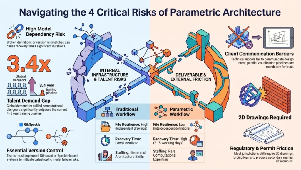
1. Model Dependency Risk
A parametric model is a single file (or a tightly coupled file system) with thousands of interdependencies. When the definition breaks—a missing data branch, a corrupted GH component, a Revit API version mismatch—the recovery time can exceed 3–5 working days. Traditional drawing sets are more resilient because each drawing is independent. Parametric teams must implement rigorous version control (Git-based or Speckle) and definition documentation or they inherit a new category of catastrophic risk.
2. Skill Scarcity
Architects who can write Grasshopper definitions at production quality—not just visual programming tutorials—are scarce. Global demand for computational designers exceeded supply by an estimated 3.4x in 2024 (per AIA Emerging Professional Survey data). This is not a software licensing problem; it is a 4–6 year training-pipeline problem. Teams that adopt parametric workflows without this skill in-house will produce technically complex models that no one can maintain.
3. Client Communication Barrier
A parametric model does not produce a legible deliverable for a client who is expecting a floor plan. The visualization pipeline—model → render → VR walkthrough—must be designed as a parallel output, not an afterthought. Teams that deliver Grasshopper screenshots to clients as design documentation lose client trust regardless of the model’s technical quality.
4. Regulatory Friction
Building departments in most jurisdictions require 2D drawing submissions for permit. Automated drawing extraction from parametric models (Phase 4) reduces but does not eliminate this friction. In jurisdictions without digital submission protocols, the parametric team must produce a full conventional drawing set as a secondary deliverable—a time cost that erodes some of the workflow’s efficiency gains.
2030 Future Projection: Where the Parametric Process Goes Next
The 5-phase structure described above is the current operational state. By 2030, 3 shifts will materially alter how each phase functions.
AI-Augmented Phase 1: Constraint Generation from Natural Language
Large language models fine-tuned on building codes, zoning ordinances, and structural standards will convert client briefs and regulatory documents directly into structured parameter sets. What currently takes 2–4 weeks of consultant meetings will take 48 hours of model inference and human review. Firms in Singapore’s BCA Building Innovation Panel are already piloting this for compliance checking in 2025.
Generative Phase 2: Foundation Model Geometry
Geometry foundation models—trained on millions of parametric definitions and structural-analysis outputs—will propose Phase 2 geometry solutions that satisfy Phase 1 constraints directly, without manual slider exploration. The architect’s role becomes evaluation and curation of generated proposals, not generation itself. Projects piloting this approach with tools like Autodesk Forma (formerly Spacemaker) report 60–70% reduction in Phase 2 elapsed time.
Closed-Loop Phase 5: Autonomous Construction Feedback
By 2030, construction robots fitted with LiDAR and computer vision will report as-built deviations to the parametric model in real time—without human data entry. The model will issue corrected fabrication files autonomously for remaining components. The as-built tolerance gap will compress from the current industry average of ±8–12 mm to ±1.5–2.0 mm on parametrically-managed sites. That is the difference between a building that performs as modelled and one that does not.
To understand the AI rendering side of this pipeline, see Nuvira’s analysis of AI architecture visualization and rendering tools.
The Toolset: 5 Key Tools for the Parametric Architecture Design Process
| Tool | Phase | Key Function |
| Grasshopper 1.0.0007 | Phase 1–3 | Visual scripting, parametric geometry, live variable binding |
| Karamba3D 2.2.0 | Phase 2–3 | Structural FEA inside Grasshopper; beam-column stress analysis |
| Ladybug Tools 1.8.0 | Phase 2 | Climate simulation: solar irradiance, wind rose, EUI projection |
| Autodesk Revit 2025.1 | Phase 4 | BIM documentation, LOD 350 coordination, IFC export |
| KUKA.PRC (Grasshopper) | Phase 5 | 8-axis robotic arm toolpath generation for fabrication |
For a comparative analysis of the rendering outputs these tools produce at the documentation stage, see Lumion vs Enscape vs D5 Render.
For the fabrication economics that determine whether parametric fabrication is cost-justified on your project, see Generative Design Cost Savings.
For how robotic fabrication integrates with Phase 5 of the parametric process, see Robotic Fabrication in Architecture.
Comprehensive Technical FAQ
Q: What software is essential to begin the parametric architecture design process?
A: The minimum viable stack is Rhinoceros 3D 8.x + Grasshopper 1.0.0007 for parametric geometry, plus Ladybug Tools 1.8.0 for environmental simulation. Add Karamba3D 2.2.0 for structural feedback. For BIM documentation, Autodesk Revit 2025.x with a Dynamo live-link to Grasshopper completes the core toolchain. You do not need all tools simultaneously at project start—Phase 1 and Phase 2 run on Rhino/Grasshopper alone.
Q: How does the parametric architecture design process handle regulatory compliance?
A: Compliance parameters are encoded in Phase 1 as hard constraints (non-negotiable upper/lower bounds) rather than aspirational targets. The model cannot generate geometry that violates them. For setbacks, FAR, and shadow angles, this is straightforward. For fire egress and accessibility—which require 2D drawing interpretation—Phase 4 automated drawing extraction enables compliance checking within the parametric workflow. Jurisdictions with digital submission systems (Singapore BCA eDASH, UK Planning Portal API) are integrating parametric model data directly.
- Hard constraint example: FAR limit 8.0 encoded as GFA ceiling in Grasshopper; model will not generate floor plates that exceed it
- Soft constraint example: Preferred courtyard width 18–22 m encoded as optimization target, not hard limit; solver finds best solution within range
Q: Can small architecture practices adopt the parametric architecture design process without a computational design specialist?
A: Yes, with important qualifications. Visual scripting in Grasshopper is learnable at a functional level in 3–6 months of consistent practice for architects with existing CAD fluency. ‘Functional’ means: building definitions from components (not writing C# or Python), running environmental simulations, and linking geometry to basic fabrication outputs.
- Phase 1 and Phase 2 are accessible at this skill level on projects up to mid-scale (say, sub-5,000 m²)
- Phase 3 structural optimization requires either Karamba3D competency or a structural engineering collaborator with parametric workflow experience
- Phase 4 BIM integration requires Dynamo scripting skill, which adds 2–3 months of additional learning
- Phase 5 construction feedback currently requires project-specific setup; no off-the-shelf solution covers all scenarios
The honest answer: a 2-person practice can run a fully parametric process on small-to-mid projects within 12–18 months of building internal competency, provided at least 1 person dedicates consistent training hours.
Q: How does the parametric process affect project fees?
A: Phase 1 setup costs are front-loaded: building the parametric definition for a new typology typically costs 1.5–2.5x a conventional design-phase fee. However, Phases 2–5 recover this cost through reduced revision hours, eliminated drawing-coordination fees, and automated documentation. Net effect on total project fee: neutral to slight reduction on first parametric project of a typology; 20–35% reduction on repeat typologies where the Phase 1 definition is reused and adapted.
- Iteration cost per design variant: near-zero (computation time only) vs. 4–12 hours in conventional workflow
- Drawing production: 40–60% reduction in hours due to automated extraction
- Coordination meetings: 30–50% reduction due to shared live model replacing sequential drawing reviews
Q: What is the difference between parametric design and generative design?
A: These terms are often used interchangeably but describe different computational modes.
- Parametric design: The architect defines the rules (parameters and their relationships). The model generates geometry when sliders change. The architect controls the exploration space.
- Generative design: An optimization algorithm (genetic algorithm, simulated annealing, etc.) autonomously explores the parameter space to find geometry that maximizes a fitness function (e.g., minimize structural weight while meeting daylighting targets). The architect defines the fitness function; the algorithm finds the solution.
In practice, the parametric architecture design process uses both: parametric geometry in Phases 1–3 for controlled exploration, and generative optimization for specific sub-problems (structural member sizing, facade panel layout, pile cap configuration) within those phases.
Q: How do the 5 phases map to a typical project timeline?
- Phase 1 (Constraint Mapping): 1–3 weeks, concurrent with design brief finalization
- Phase 2 (Geometry + Simulation): 3–8 weeks, replacing conventional schematic design stage
- Phase 3 (Structural + Fabrication Optimization): 4–8 weeks, replacing design development stage
- Phase 4 (BIM Documentation): 4–6 weeks, replacing construction documents stage
- Phase 5 (Construction Feedback): Concurrent with construction, project-length commitment
Total pre-construction elapsed time: 12–25 weeks depending on project scale, vs. 20–40 weeks for equivalent conventional workflow. The compression is real, but it front-loads skill and setup costs.
The Only Question Left Is When You Start
The parametric architecture design process is not a future workflow. It is the current workflow of every firm producing architecture that competes on performance, precision, and construction efficiency. The firms that have not yet adopted it are not protecting a superior method—they are accruing a compounding technical debt: slower revision cycles, higher coordination costs, and fabrication tolerances that make complex form economically inaccessible.
The 5 phases described above are operational—you can begin Phase 1 on your next project tomorrow. Encode your constraints. Build your parameter file. Let the model work. The question is not whether the parametric process will replace your current workflow. It already has, for the projects you want to be winning.
Explore Nuvira’s analysis of generative AI in architecture for the next layer of the computational design stack.
© Nuvira Space · All rights reserved. | Future Tech Series | All specifications cited are based on published parametric project documentation, Grasshopper/Rhino official release notes (versions 1.0.0007 and 8.x respectively), Karamba3D 2.2.0 documentation, Ladybug Tools 1.8.0 changelog, KUKA.PRC toolpath specification, Singapore BCA Green Mark Platinum standard 2023, Autodesk Revit 2025 release notes, and AIA Emerging Professional Survey 2024 data.
The Lattice_Kota project is a speculative internal concept study and does not represent a completed or commissioned project.