

Table of Contents
Macro-Observation Hook
Every architectural office that has replaced perspective sketches with isometric architecture illustration reports the same result: client approval cycles drop, contractor coordination errors shrink, and the drawings themselves start functioning as construction documents rather than decorative aids. The reason is structural, not aesthetic — isometric projection eliminates vanishing points, keeps all three axes dimensionally honest, and produces a drawing that scales without distortion. Mastering this workflow is no longer optional for a visualization studio operating at professional throughput.
NUVIRA PERSPECTIVE. We Don’t Illustrate Buildings. We Decode Them.
At Nuvira Space, the isometric architecture illustration is not a style choice — it is a systems language. Where perspectival rendering seduces through vanishing points and focal blur, isometric projection demands dimensional discipline. Every face of a structure must account for itself. You cannot hide a poorly resolved floor-to-ceiling height inside atmospheric haze or a carefully positioned entourage tree. The drawing either holds at 1:1 across all three axes, or it doesn’t hold at all. This is the standard we apply to every Visual Lab study: not what looks compelling at small scale, but what survives technical interrogation at full resolution.
The convergence of parametric BIM workflows, Blender’s Cycles and EEVEE rendering engines, and vector post-production in Adobe Illustrator has created a pipeline where isometric illustration is no longer a hand-drafting discipline — it is a precision digital workflow that sits at the intersection of geometry, light simulation, and graphic systems design. This guide walks you through that pipeline in six measurable steps, from grid calibration to final export, with the hardware checkpoints and advanced techniques that separate a professional deliverable from a student exercise.
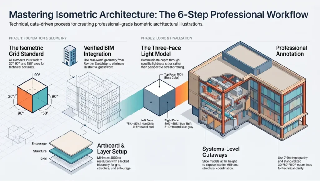
Step-by-Step Workflow: How to Master Isometric Architecture Illustration in 6 Steps
Step 1 — Grid Architecture and Document Setup
Before a single line exists, the isometric grid defines everything that follows. Errors made at this stage compound through every subsequent step with no recovery path.
In Adobe Illustrator:
- Open Effect > 3D and Materials > Inflate (deprecated in newer versions) or use the legacy Effect > 3D > Extrude & Bevel with the Isometric Top / Left / Right presets
- For manual grid construction, use the Line Segment Tool at 30° and 150° on the horizontal axes, and 90° for all vertical elements
- Set Keyboard Increment in Preferences > General to 28px for grid snapping consistency
- Create a Symbol Library of base isometric cubes at 39.6px extrude depth — this becomes your modular building block
Recommended document specifications:
- Artboard: 4000 × 4000px minimum for print-grade output
- Color Mode: CMYK for print, RGB for screen; never mix
- Grid visible via View > Show Grid with Snap to Grid active
- Layer structure: Grid (locked) / Structure / Entourage / Annotation / Export
In Blender (for 3D-sourced isometric output):
- Set camera to Orthographic projection
- Set camera rotation to X: 54.736°, Z: 45° — this is the mathematically correct isometric camera position
- Lock camera to view: View > Lock Camera to View disabled; use Numpad 0 to return to camera
- Set Focal Length is irrelevant in orthographic mode; adjust Orthographic Scale to frame the model
Grid Calibration Checklist
- [ ] All axes locked to 30°/90°/150°
- [ ] Base module defined and saved as symbol
- [ ] Layer naming convention confirmed before drawing begins
- [ ] Export profile created (PDF/X-1a for print, SVG for web)
Step 2 — Structural Massing from BIM or CAD Source
Isometric architecture illustration executed without source geometry is illustrative guesswork. The professional pipeline begins with verified building data.
Revit to Illustrator pipeline:
- In Revit, create a 3D View named “ISO_EXPORT”
- Set View Properties > Discipline to Architectural
- Enable Isometric view type via the View Cube or Properties panel (note: Revit’s native isometric is axonometric — confirm rotation matches your Illustrator grid)
- Export via File > Export > CAD Formats > DWG, selecting Isometric Projection with Layer/Color by Category
- Import DWG into Illustrator via File > Place or Open — choose Fit Page and verify scale against your grid module
SketchUp to Blender pipeline (for complex massing studies):
- Export from SketchUp as .OBJ or .FBX with Triangulate All Faces disabled
- Import into Blender: File > Import > Wavefront (.obj)
- Clean geometry: Edit Mode > Select All > Merge by Distance (threshold: 0.001m)
- Apply Decimate modifier (Ratio: 0.3–0.5) for illustration-weight poly counts — you are rendering a diagram, not a photorealistic model
Pro Specification Notes
- Always work in real-world units (meters or millimetres) — never “illustration units”
- Floor-to-floor height: 3.0m residential standard, 4.2m commercial standard
- Column grid: verify against structural drawings before illustrating — isometric drawings expose column misalignment that perspective hides
Step 3 — Light Logic and Face Value Assignment
Isometric illustration communicates depth through face value differentiation, not perspective foreshortening. The standard three-face light model is non-negotiable.
The Three-Face Light Model:
- Top face: lightest value — represents the sky plane / direct illumination
- Left face: mid value — represents ambient / diffuse bounce
- Right face: darkest value — represents shadow / shade face
The value ratio that reads cleanest at print scale:
- Top: 100% base color lightness
- Left: 75–80% base color lightness (Hue Shift: 0–5° toward cool)
- Right: 50–60% base color lightness (Hue Shift: 5–10° toward blue-grey)
In Illustrator, apply via:
- Object > Transform > Shear to map flat rectangles onto isometric planes
- Apply fill via Appearance Panel using Multiply blending for shadow faces over a white ground
- For gradient faces: use Linear Gradients locked to the 30° axis of each plane
In Blender (for rendered isometric output):
- Use EEVEE render engine for illustration-style output (not Cycles — Cycles introduces sub-surface scattering and noise inappropriate for technical illustration)
- Sun lamp: Rotation X: 45°, Y: 0°, Z: 135° — upper-left key light
- World Ambient Occlusion: enabled, Distance: 0.5m, Factor: 1.0
- Color Management > Look: set to None or Very Low Contrast — preserve flat illustration tones
- Render resolution: 4000 × 4000px, samples: 32–64 (EEVEE) — higher samples unnecessary for flat illustration style
Step 4 — Detail Injection and Entourage Systems
At this step, the illustration gains its communicative density — windows, structural reveals, landscape, human figures, and material texture.
Window and Facade Systems:
- In Illustrator, create Symbol Libraries for window types (curtain wall, punched opening, louvered screen) — each symbol set must have three isometric variants (top, left-facing, right-facing)
- Window-to-wall ratio: match the source architectural drawings — do not increase glazing for visual effect
- Structural reveals: 0.5–1.0px stroke at print scale, 2–4px at screen resolution
Landscape entourage — isometric tree construction:
- Base canopy: circle scaled to 86.6% on the horizontal axis (this is the isometric compression ratio — cos(30°) = 0.866)
- Trunk: vertical line segment only — no perspective lean
- Shadow: offset ellipse at 30°, filled with shadow value (50% opacity, Multiply)
Human figures at isometric scale:
- Standard figure height: 1.75m in real-world units
- At 1:200 scale: 8.75mm = approximately 25px at 72dpi screen resolution
- Use simplified silhouette figures — high-detail figures conflict with the diagrammatic nature of isometric illustration
Material texture application:
- Brick: repeating isometric pattern fill, brick module 230mm × 76mm standard
- Concrete: solid flat tone with no texture — isometric reads texture as noise
- Glazing: 30% opacity fill on right and left faces; top face: 50% opacity. Refer to texture mapping workflows in texture mapping for photorealistic renders for how these values translate to rendered output.
Step 5 — Cutaway Section and Systems Coordination
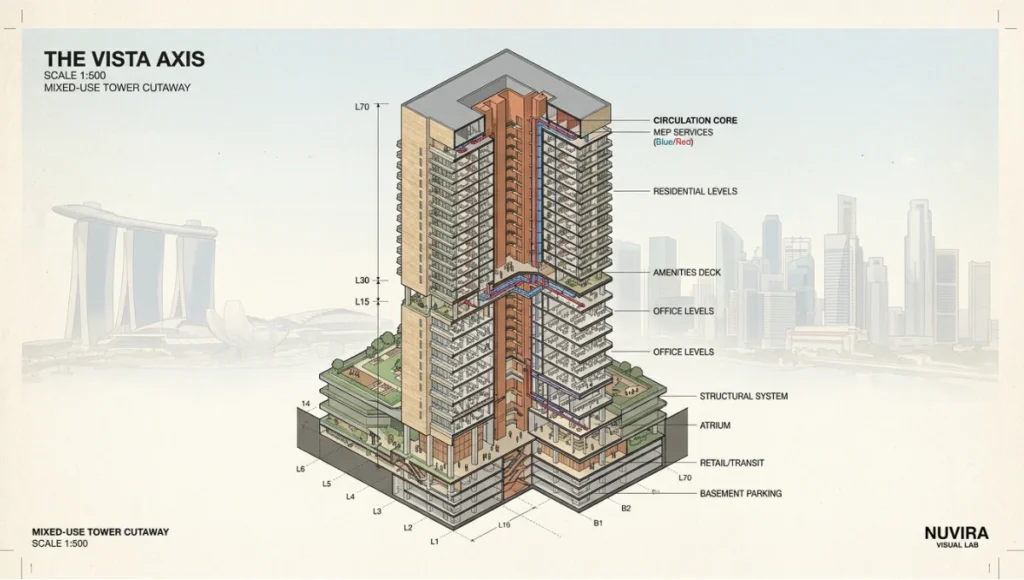
The cutaway isometric is the highest-value drawing type for client communication, contractor coordination, and planning authority submissions. It exposes interior spatial relationships, MEP routing, and structural logic within a single unified view.
Cutaway construction method in Illustrator:
- Duplicate the complete building illustration to a locked reference layer
- On the working layer, select and delete all faces above the cut plane
- Cut plane is typically at 1m above finished floor (sill height) — this exposes rooms without removing roof structure
- Redraw exposed interior faces using interior material values (lighter palette than exterior)
- Add hatch patterns for structural elements: 45° crosshatch for reinforced concrete sections, horizontal lines for timber
MEP (mechanical, electrical, plumbing) layer:
- Ductwork: rectangular sections, colour-coded (blue: supply air, red: return air, green: exhaust)
- Pipe runs: circular section symbols on isometric routing paths
- Electrical conduit: thinner stroke weight than structural, dashed line convention
For BIM-sourced cutaways:
- In Revit: create a Section Box in the 3D view cropped to the cut plane
- Export the cropped view as DWG for Illustrator cleanup
- In Blender: use Boolean Modifier (Operation: Difference) with a cutting cube object to slice the model before camera render
This systems-level approach connects directly to the parametric coordination methods described in generative design cost savings — where drawing precision at the illustration stage reduces downstream RFI volume.
Step 6 — Post-Production, Annotation, and Export
The final step separates a technically correct drawing from a professionally deployable deliverable. Post-production in Illustrator defines legibility across all output formats simultaneously.
Typography and annotation system:
- Primary labels: Helvetica Neue Light or Inter, 7–9pt at print scale
- Leader lines: 0.5pt stroke, elbow at 90°/30°/150° — never freehand curves
- Dimension strings: architectural convention — extension lines perpendicular to measured face, arrowheads at 45°, text above dimension line
- North indicator: always include on isometric site plans — orient to match the true orientation of the building
Colour system for deliverable variants:
- Presentation layer: full colour, shadow faces active, entourage complete
- Technical/consultant layer: reduced colour, structure and systems emphasised, entourage removed
- Greyscale/print layer: convert all fills to greyscale, verify minimum 30% value contrast between adjacent faces
Export specifications:
- Print deliverable: PDF/X-1a, 300dpi embedded, CMYK, trim marks active
- Digital deliverable: SVG (preserves scalability), or PNG at 144dpi for screen
- Client presentation: AI native file locked with password protection — never send editable source files to clients
Comparative Analysis: Nuvira Isometric Workflow vs. Industry Standard
What the Industry Standard Actually Produces
The prevailing industry approach to isometric architecture illustration follows one of two paths: a Revit 3D export cleaned up in AutoCAD and printed at insufficient resolution, or a hand-drafted isometric traced over a photograph or plan at inconsistent scale. Both approaches share the same structural flaw — they prioritise output speed over dimensional integrity.
Where the Nuvira Workflow Differs
| Criterion | Industry Standard | Nuvira Visual Lab Workflow |
|---|---|---|
| Source geometry | Photograph trace / plan sketch | Verified BIM or CAD source |
| Scale consistency | Visual approximation | Real-world units, locked grid |
| Light model | Intuitive shading | Three-face value ratio, defined ratio |
| Cutaway production | Manual redraw | Boolean section + BIM crop |
| Export variants | Single-use file | Master file with layer-switched variants |
| Annotation | Added last, inconsistent | Type system defined pre-drawing |
The quantitative gap becomes visible in revision speed. A drawing produced without a locked grid and symbol library requires a full redraw on scope change. A drawing built on the Nuvira grid system requires only symbol substitution and layer visibility adjustment — revision time drops by approximately 60–70% on complex mixed-use typologies.
When Perspective Rendering Still Wins
Isometric illustration does not replace perspectival visualization — it serves a different communicative function. For client emotional engagement, contextual site visualization, and marketing material, AI architecture visualization rendering and real-time rendering tools remain the correct choice. Isometric illustration is the precision instrument; perspective rendering is the experiential instrument. A professional studio deploys both.
Concept Project Spotlight
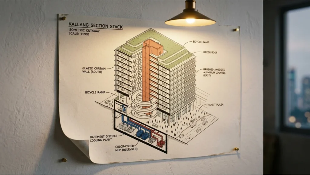
Speculative / Internal Concept Study — “Kallang Section Stack” by Nuvira Space
Project Overview (Location / Typology / Vision)
Location: Kallang River District, Singapore
Typology: Mixed-use transit-oriented infill, 12-storey
Vision: A vertically stacked neighbourhood block positioned above the Kallang MRT interchange, designed to demonstrate how isometric cutaway illustration can replace a conventional set of twenty separate architectural drawings in a single coordinated document.
Singapore’s Urban Redevelopment Authority has invested significantly in 3D digital urban modelling since the Virtual Singapore initiative — a national-scale 3D city model integrating topography, building density, traffic flows, and resource consumption data. The Kallang district sits at the intersection of multiple transit corridors, making it one of the most spatially complex infill sites in Southeast Asia. The “Kallang Section Stack” speculative study uses this real urban context to test what a fully isometric illustrated document set looks like when built from verified geometry.
Design Levers Applied
Structural Grid:
- Column grid: 8.4m × 8.4m — commercial standard, enables residential conversion
- Floor-to-floor: 3.6m throughout — satisfies both commercial (minimum 2.7m clear) and residential (minimum 2.4m clear) programming
- Core location: offset core at NE corner — frees south-facing facade for full glazed curtain wall
Isometric Illustration Specifications:
- Drawing scale: 1:200 master, 1:50 detail cutaways
- Cut plane: 1.2m above FFL per floor — captures window sill, reveals MEP above ceiling, retains structural depth visible
- Face value ratio: Top 100% / Left 78% / Right 54% — calibrated for Singapore’s high-contrast equatorial light conditions
- Colour palette: Cool grey base (#B2B8C4) with warm terracotta accent (#C4714A) for vertical circulation cores — legible at both A1 print and on-screen presentation
Systems Illustrated:
- District cooling connection shown at basement level
- Green roof strata: waterproofing layer / drainage cell / growing medium / planting — each layer in isometric section hatch
- Bicycle ramp integrating ground-level MRT connectivity
Transferable Takeaway
The Kallang Section Stack demonstrates one transferable principle applicable to any isometric project: the cut plane altitude determines the drawing’s communicative priority. A cut at 0.9m (datum: floor) reads structural; a cut at 1.2m (sill height) reads spatial; a cut at 2.4m (ceiling plane) reads systems. Choose the altitude based on the audience, not on aesthetic preference.
Intellectual Honesty: Hardware Check
Isometric illustration in Illustrator is not computationally expensive — a mid-range workstation handles complex vector files without difficulty. However, the Blender-sourced portion of the pipeline has real hardware requirements that directly affect output quality.
Minimum specification for isometric Blender renders at 4000 × 4000px:
- GPU: NVIDIA RTX 3060 12GB VRAM or AMD RX 6700 XT 12GB VRAM
- RAM: 32GB DDR4 — complex BIM-imported models with geometry cleanup require headroom
- Storage: NVMe SSD — Blender’s rendered output cache writes continuously during render
- CPU: Secondary to GPU for EEVEE; for Cycles, 8-core minimum recommended
Where hardware limitations visibly affect output:
- Below 8GB VRAM: Blender will fall back to CPU rendering on complex scenes — render times increase 4–8× for the same output
- Below 16GB RAM: large DWG imports crash Illustrator on complex mixed-use drawings
- Spinning HDD storage: render cache writing creates visible stuttering in Blender’s viewport, slowing workflow even if final output is unaffected
Pragmatic alternative for constrained hardware: Use Illustrator exclusively, sourcing geometry from Revit DWG exports without Blender. The visual output is marginally less refined in terms of ambient occlusion and soft shadow, but the dimensional accuracy is identical. The best GPU for rendering 2026 comparison covers the current hardware landscape in detail if you are evaluating a workstation upgrade to support this pipeline.
2030 Future Projection
Three converging developments will fundamentally change what isometric architecture illustration is and who produces it by 2030.
1. Parametric Isometric Generation from BIM Revit, ArchiCAD, and their successors are moving toward direct isometric output as a native drawing type rather than a post-production export. By 2027–2028, it is probable that a BIM model will generate a correctly configured isometric illustration set — with face values, cutaway options, and annotation — automatically on view creation. The illustrator’s role shifts from drawing production to drawing curation and editorial decision-making.
2. Real-Time Isometric Rendering Unreal Engine 5’s Nanite geometry system and Lumen global illumination are already capable of rendering orthographic isometric views in real time. The current constraint is workflow — architects do not yet have an efficient path from BIM to UE5 that preserves dimensional accuracy. By 2030, this pipeline will be standardised. Isometric illustration will become a live, interactive deliverable rather than a static document.
3. AI-Assisted Detail Injection The most time-consuming element of isometric illustration — populating a building with correctly scaled entourage, material texture, and annotation — is already partially automatable via generative AI pattern fill and AI-assisted symbol placement. By 2030, a competent illustrator will generate a draft isometric at production quality in 20–30% of the current time, with the remaining effort focused on technical verification and editorial refinement rather than drawing mechanics.
The implication for studios investing in this skill now: the drawings you produce manually in 2025 are training the intuition and quality benchmark for the systems that will produce them semi-automatically in 2030. The technical knowledge embedded in this guide does not become obsolete — it becomes the specification against which automated output is measured.
Secret Techniques: Advanced User Guide
These are the workflow accelerators that do not appear in official documentation.
01. The Isometric Action Stack in Illustrator Build a saved Action for each of the three face orientations:
- ISO_TOP: Shear 0°, Scale Y 86.6%
- ISO_LEFT: Shear -30°, Scale Y 86.6%, Rotate 30°
- ISO_RIGHT: Shear 30°, Scale Y 86.6%, Rotate -30°
Assign keyboard shortcuts to each action. On a complex building, this reduces face-mapping time by approximately 40% compared to manual Transform panel entry.
02. Blender’s “Orthographic Compositor” Technique Render the building in three separate passes — structure only / shadow pass / entourage only — using Blender’s Compositor and render layers. Combine in Illustrator as separate placed images. This gives you independent control over shadow density and entourage opacity in post-production without re-rendering.
03. The Isometric Grid Overlay in Photoshop For projects where the final illustration combines rendered texture with vector line work, place an isometric grid as a Photoshop Smart Object overlay set to Multiply at 8–12% opacity. This creates a subtle technical register that anchors the illustration to its diagrammatic function without overpowering material texture.
04. Scale Verification via the “1-Metre Calibration Object” Before any drawing work begins in Illustrator, place a 1m × 1m × 1m isometric cube in the corner of your artboard. At your working scale, this cube becomes your dimensional reference. Every subsequent element is sized relative to it. This eliminates scale creep — the gradual drift that occurs when elements are drawn by eye without a fixed reference.
05. Layered Transparency for Construction Phasing For projects requiring phasing diagrams, build each construction phase on a separate Illustrator layer. Set Phase 1 at 100% opacity, Phase 2 at 60%, Phase 3 at 30%. Export each layer visible state as a separate artboard. The result is a phasing animation that requires no After Effects — simply sequence the exported frames. This technique also applies to architectural animation workflows when isometric frames are used as a base.
Comprehensive Technical FAQ
Q: What is the mathematically correct isometric camera angle in Blender?
A: The camera requires two rotations to achieve true isometric projection:
- X rotation: 54.736° (this is arctan(√2) ≈ 54.7356°)
- Z rotation: 45°
Combined with Orthographic projection (not Perspective), this produces a view where all three principal axes are equally foreshortened and appear at 120° to each other. Many tutorials round to 54.74° or 55° — this is acceptable for illustration purposes but will produce measurable error in dimensionally critical drawings.
Q: What is the difference between isometric and axonometric projection?
A: Isometric is a subset of axonometric projection. In true isometric:
- All three axes are equally foreshortened (foreshortening ratio: 0.816)
- All three axes appear at 120° to each other in the projected view
Other axonometric types (dimetric, trimetric) use different foreshortening ratios per axis. For architectural illustration, isometric is the standard because it allows direct measurement along all axes at a consistent scale. For more expressive or diagrammatic work, dimetric projection (typically 7°/42° axis angles) produces a more dynamic composition.
Q: Can Revit export true isometric views directly?
A:
- Revit’s 3D views use parallel projection when the “Isometric” option is selected in the View Properties panel
- The native export is axonometric, not true isometric — axis angles depend on the model’s orientation
- For true isometric alignment: rotate the 3D view so that the building’s primary axes align with Revit’s default isometric preset, then export
Recommended workflow:
- Export as DWG with “Isometric Projection” active
- Verify axis angles in Illustrator against your pre-built grid
- Correct any discrepancy by rotating the imported DWG
Q: How do I handle curved geometry in isometric illustration?
A: Curved geometry — arched openings, cylindrical columns, domed roofs — requires ellipses, not circles. The isometric ellipse specifications:
- Top-facing circle: ellipse with Width: diameter × 1.0, Height: diameter × 0.577 (tan 30°)
- Left-facing circle: rotate 30° clockwise from top
- Right-facing circle: rotate 30° counter-clockwise from top
In Illustrator, use Effect > 3D > Rotate on a circle with the correct isometric rotation applied — this gives a live effect that updates if the circle is resized.
Q: What colour palette works best for isometric architecture illustration?
A:
- Avoid saturated primaries — they conflict with the structural clarity of the drawing
- Recommended base palette: cool neutrals (grey-blues, warm stones) with single accent colour for primary programme or circulation
- Face value differentiation is more important than colour choice — maintain a minimum 20% lightness difference between top, left, and right faces at all times
- For multi-building site plans: assign each building a distinct hue but keep saturation below 40% — this maintains legibility without the illustration reading as a branding exercise rather than a technical document
Q: How do I size the drawing for different output formats?
A:
- A1 plot (841mm × 594mm) at 300dpi: artboard 9921 × 7016px
- A3 plot (420mm × 297mm) at 300dpi: artboard 4961 × 3508px
- Screen presentation (16:9): artboard 3840 × 2160px (4K UHD)
- Social media (square): artboard 3000 × 3000px
Always build at the largest required output and scale down — never upscale a completed illustration.
Build the Technical Foundation Your Renders Can’t Replace
Isometric architecture illustration is not a style. It is a precision drawing discipline that encodes dimensional truth into every line — and when executed correctly, it produces documents that serve clients, planners, contractors, and your own design development simultaneously.
The six-step workflow in this guide gives you the technical foundation: grid discipline, BIM-sourced geometry, calibrated light logic, systems-level cutaway construction, post-production rigour, and export-ready deliverable management. Layer the advanced techniques on top — the action stacks, the Blender compositor passes, the 1-metre calibration object — and you have a pipeline that scales from a single residential project to a complex mixed-use district like the Kallang case study without fundamental process change.
Apply what you have read here to your next project. Build the grid before the drawing. Define the light model before the fill. Set the annotation system before the entourage. The sequence is the discipline, and the discipline is the skill.
Explore how isometric illustration integrates with AI-assisted design tools in AI architecture design tools, and see how the parametric thinking behind this workflow connects to architecture mood board creation at the concept development phase.
© Nuvira Space — All rights reserved. | THE VISUAL LAB Series | All specifications cited are based on Adobe Illustrator 2025 documentation, Blender 4.x official render pipeline parameters, Autodesk Revit 2025 export specifications, and general isometric projection standards per ISO 5456-3:1996 (Technical drawings — Projection methods — Part 3: Axonometric representations). The "Kallang Section Stack" is a speculative internal concept study and does not represent a completed project.