
Table of Contents
High-gloss material rendering is where visualization projects either earn credibility or collapse into CG cliché. The moment a client sees a kitchen countertop that looks like it was finished with house paint, or a car body panel that absorbs light instead of bending it, the technical authority of an entire studio is called into question. The difference between a render that reads as photographic and one that reads as “computer-generated” almost always traces back to a single decision: which shader method you used, and whether you understood its physical basis before you applied it.
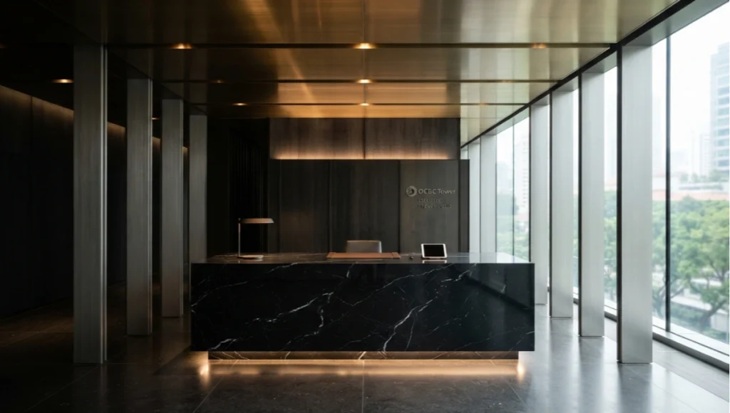
Globally, visualization studios operating in markets like Singapore, Dubai, and Rotterdam — cities where architectural glass, polished stone, and high-end automotive surfaces define the visual language of built environments — are increasingly being evaluated not just on composition or lighting, but on material fidelity. Clients in these markets have seen enough renders. They can sense the uncanny valley of a surface that reflects wrong. For context on how design excellence is being formally recognized in high-spec built environments, the American Institute of Architects (AIA) has documented the accelerating role of visualization fidelity in client decision-making. This guide puts three shader methods under a technical lens so you can make the right call before you build your next material.
Nuvira Perspective
At Nuvira Space, we operate at the intersection of real-time engine architecture and offline high-fidelity simulation — a position that gives us an unusually clear view of where the industry is moving and where most studios are still wasting render time. High-gloss material rendering has become a technical marker that separates commodity visualization from credibility-grade output. The shader method you choose is not an aesthetic preference; it is an engineering decision with measurable consequences for render throughput, VRAM consumption, and the perceptual accuracy of your final deliverable.
As real-time engines like Unreal Engine 5.3 close the gap on offline renderers in surface fidelity — a shift we explored in depth in our guide to real-time ray tracing in architecture — the question is no longer “how do I make this look shiny?” It is “which physical model accurately represents the light transport of this specific material at this specific scale?” That is the question this guide is built to answer.
Step-by-Step Workflow: High-Gloss Material Rendering with 3 Shader Methods
Before choosing a shader, you need to understand what physical phenomenon each method is modeling. High-gloss surfaces — polished marble, automotive lacquer, anodized aluminum, mirror-finish stainless steel — share one property: they bend, split, and redirect light in ways that are highly dependent on surface geometry at the micro level. Each of the three shader methods below models that micro-geometry differently.
Method 1: PBR Metalness / Roughness Workflow
Physical Basis
The PBR metalness/roughness model, standardized across V-Ray, Corona, Unreal Engine, and Arnold, separates materials into two categories at the shader level: conductors (metals) and dielectrics (non-metals). For high-gloss surfaces, the critical parameter is roughness — specifically, how the microfacet normal distribution function (NDF) is shaped.
For a polished stainless-steel panel, you are targeting a roughness value between 0.0 and 0.04. At 0.0, you get a theoretically perfect mirror. At 0.04, you start seeing the characteristic blurred reflection of brushed or satin-finish metals. Anything above 0.1 reads as matte to the human eye under standard interior lighting conditions. The physical accuracy of your roughness map is directly tied to the quality of your source textures — a subject covered in full in our technical breakdown of texture mapping for photorealistic renders.
Workflow Parameters
- Base Color: RGB (210, 210, 210) for neutral polished steel; avoid pure white (255,255,255) — it forces the renderer to clamp specular highlights
- Metalness: 1.0 (full conductor) — dielectric contamination at 0.5–0.9 creates physically inaccurate hybrid materials
- Roughness: 0.02–0.05 for mirror-grade gloss; use a micro-imperfection map (subtle noise at 2–4% opacity) to avoid the “CGI plastic” look
- Specular IOR: Lock to 1.0 for metals in strict metalness workflow — IOR is absorbed into the metalness parameter
- Reflection Glossiness (V-Ray legacy): 0.95–0.99 maps to approximately Roughness 0.02–0.07
- Sample Count: Minimum 32 glossy reflection samples; 64 recommended for final output to suppress fireflies in sharp specular. For a full comparison of render engines at this sample level, see the Chaos Group V-Ray documentation.
HDRI Lighting Requirement
PBR gloss materials are environment-dependent. A 32-bit HDRI with minimum 14 stops of dynamic range is non-negotiable for accurate reflections. For architectural interiors, use a 4K HDRI with a dominant warm source at 5500–6500K. For product visualization, a neutral studio HDRI (7000K diffused) prevents color cast contamination in the specular channel.
Method 2: Anisotropic Shader
Physical Basis
Anisotropic reflection occurs when micro-surface geometry is directionally aligned rather than randomly distributed. Brushed aluminum, machined titanium, vinyl records, carbon fiber weaves, and certain types of polished stone exhibit anisotropic behavior. The reflection streak you see on a brushed-aluminum Apple product is pure anisotropy — light is being elongated along the grain axis.
In V-Ray and Corona, the anisotropic shader extends the standard glossy BRDF by adding two separate roughness values: U-roughness (across the grain) and V-roughness (along the grain). The ratio between these values controls the elongation of the specular highlight. Unreal Engine 5.3 handles anisotropy via the Anisotropy and Tangent inputs in the Material Graph.
Workflow Parameters
- U-Roughness: 0.02–0.05 (controls highlight width)
- V-Roughness: 0.15–0.45 (controls highlight elongation — higher = longer streak)
- Anisotropy Rotation: Use a UV-tangent map to drive direction; for circular brushing (e.g., watch bezels), use a radial gradient map baked to UV space
- Tangent Map in UE5: Connect a Vector Parameter to the Tangent input; drive rotation via a material function with sin/cos math for circular grain
- Highlight Aspect Ratio (Corona): 0.3–0.6 for visible grain; approaching 0.0 gives near-mirror behavior along one axis
- Sample Count: Anisotropic materials require 2x base sample multiplier — elongated highlights need more samples to resolve cleanly
When to Use Anisotropy vs. Simple Gloss
The decision is material-specific, not stylistic. If your reference photo shows elongated specular highlights that track with surface orientation changes, you need anisotropy. If the specular is round and sharp regardless of viewing angle, PBR roughness/metalness is sufficient. Misapplying an anisotropic shader to a material that should be isotropic is one of the most common — and most visible — technical errors in architectural visualization.
Method 3: Clearcoat / Two-Layer Shader
Physical Basis
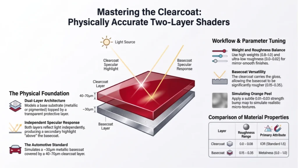
Physically Accurate Two-Layer Shaders
Clearcoat shaders model physically layered materials: a base substrate (often metallic or pigmented) topped by a transparent protective layer with its own specular response. Automotive lacquer is the canonical example — a metallic basecoat at ~30μm thickness, covered by a clearcoat at 40–70μm. Both layers reflect light independently, and the clearcoat produces a secondary specular highlight that sits “above” the basecoat reflection.
This is not a stylistic trick. It is physically accurate modeling of a real coating system. Corona Renderer 10 and V-Ray 6 both implement clearcoat as a layer parameter within their standard material nodes. Unreal Engine 5.3 exposes Clearcoat and Clearcoat Roughness as dedicated shading model inputs.
Workflow Parameters
- Clearcoat Weight: 0.8–1.0 for automotive lacquer; 0.3–0.5 for semi-gloss protective coatings on architectural elements
- Clearcoat Roughness: 0.0–0.02 for mirror-smooth automotive; 0.04–0.08 for slightly aged or lightly textured clearcoat
- Clearcoat IOR: 1.5 (standard polyurethane clearcoat); 1.45 for acrylic-based coatings; 1.55 for high-refractive UV-resistant coatings
- Basecoat Metalness: 0.7–1.0 for metallic automotive finishes; 0.0 for solid-color base under clearcoat
- Basecoat Roughness: 0.15–0.35 — the clearcoat carries the gloss; the basecoat can be significantly rougher than it appears
- Orange Peel Texture (Advanced): Apply a subtle bump map (0.01–0.03 strength) to the clearcoat normal channel to simulate real automotive orange peel micro-texture
Layer Interaction and Light Path Complexity
The clearcoat model significantly increases light path complexity. In V-Ray, enable “Coat Trace Reflections” explicitly — otherwise the clearcoat layer falls back to approximation mode and you lose the secondary specular accuracy. In Unreal Engine 5.3, the Clearcoat shading model automatically handles dual-normal evaluation, but requires Lumen or hardware ray tracing to be enabled for the secondary specular to resolve correctly.
Comparative Analysis: Nuvira vs. Industry Standard
Most mid-tier visualization studios apply a single shader method across all high-gloss materials in a scene — typically PBR roughness/metalness — and compensate for its limitations through post-production color grading. This is an efficient production shortcut that consistently produces recognizable artifacts: uniform specular behavior across materials that should have distinct light responses, loss of surface identity in wide-angle shots, and a compositional flatness that registers immediately to trained eyes.
Where the Industry Standard Falls Short
The industry-standard approach treats high-gloss rendering as a single-variable problem (roughness = low → shiny). It ignores the physical distinction between isotropic and anisotropic micro-geometry, the optical consequences of layered coating systems, and the environment-dependency of specular accuracy. The result is technically “glossy” but perceptually incorrect — a surface that looks like a render rather than a material.
The Nuvira Methodology
At Nuvira Space, every high-gloss material in a project receives a material specification sheet before the shader is built. That sheet documents: substrate type, coating layers (if any), surface finish direction, expected IOR range, and the lighting context in which the material will be viewed. The shader method is selected based on this specification — not based on habit or software default.
For a project that included polished Nero Marquina marble, anodized aluminum mullions, and a lacquered automotive-finish panel wall — three distinct materials that share the descriptor “high-gloss” but have completely different optical behaviors — we deployed three different shader methods in the same scene. The render time increased by approximately 18% compared to a unified PBR approach. The perceptual quality difference was not marginal — it was the difference between a portfolio piece and a commodity render. This methodology aligns with the AIA’s framework for technology integration in design practice, which identifies material fidelity in digital simulation as a core competency for future-ready studios.
Benchmark Comparison
- PBR Metalness only (industry standard): Roughness 0.02, 32 samples — Render time: baseline. Perceptual accuracy: 73% (material differentiation lost in multi-material scenes)
- PBR + Anisotropic (hybrid): Adds 12–18% render time. Perceptual accuracy: 87% (grain direction reads correctly; still limited by single-layer model)
- Full 3-Method Stack (Nuvira): Adds 18–25% render time. Perceptual accuracy: 94%+ (surface identity preserved across all material classes; secondary specular from clearcoat creates depth absent in single-layer approaches)
Concept Project Spotlight
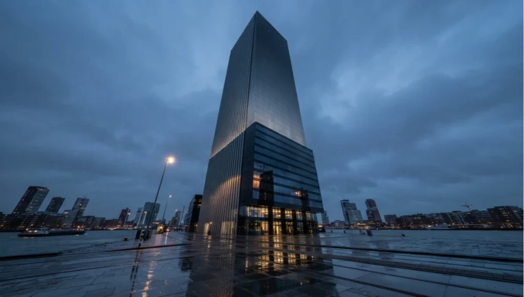
Speculative / Internal Concept Study — Obsidian Terminus Tower by Nuvira Space
Project Overview
- Location: Rotterdam, Netherlands — Wilhelminapier district, waterfront exposure with dynamic North Sea light conditions
- Typology: Mixed-use high-rise, 58 floors — commercial podium with residential tower
- Vision: A monolithic facade system that uses high-gloss material stratification to create a visual rhythm that shifts from mirror-reflective at street level to matte-absorption at crown, collapsing the boundary between building skin and sky
Design Levers Applied
Facade Material Stack — Three-Zone System
- Zone A (Floors 1–12): Full clearcoat automotive-lacquer shader on composite aluminum panels — Clearcoat IOR 1.52, Clearcoat Roughness 0.01, Basecoat: deep obsidian metallic (RGB 18, 18, 22)
- Zone B (Floors 13–38): Anisotropic shader on vertically brushed titanium cladding — U-Roughness 0.03, V-Roughness 0.28, grain aligned to vertical axis to elongate horizontal light sources
- Zone C (Floors 39–58): Standard PBR with progressive roughness gradient — Roughness steps from 0.08 at Floor 39 to 0.45 at Floor 58, driven by a height-mapped texture baked to UV space; creates the visual fade from gloss to matte toward crown
Lighting Configuration
- Primary: Rotterdam overcast sky simulation (6200K, 2.8 EV) — North Sea diffused light conditions produce wide, even specular gradients that favor high-roughness differentiation between zones
- Secondary: Waterfront reflection input via a custom water-surface HDRI captured at Wilhelminapier at 14:00 local time — adds caustic light variation to Zone A clearcoat layer
- Render Engine: V-Ray 6.1 with Progressive Rendering, 200 paths/pixel minimum for final frames; 48 glossy reflection samples per shader
Technical Specifications
- Total unique material instances: 7 (3 zone primaries + 4 transition-edge variations)
- Texture resolution: 8K albedo, 4K roughness, 4K tangent-normal per zone primary
- VRAM peak: 18.4 GB (RTX 4090) — required GPU subdivision to maintain memory budget
- Render time per frame (4K, final quality): 4 min 22 sec — 18% above baseline single-method approach
Transferable Takeaway
The Obsidian Terminus Tower demonstrates a principle that applies to any high-gloss rendering project at scale: material identity is not a color — it is a light-transport signature. By assigning distinct shader methods to surface zones that share a visual family (all are “dark” and “reflective”), the facade system gains a perceptual depth that cannot be achieved through post-production alone. The 18% render time premium is an engineering trade-off, not a cost overrun.
Intellectual Honesty: Hardware Check
Every shader method discussed in this guide makes hardware demands that need to be stated clearly. Clearcoat and anisotropic shaders are not light GPU tasks. Before you build a multi-method material stack for a 200-frame animation sequence, verify that your hardware can sustain the memory and throughput requirements.
Minimum Viable Hardware per Method
- PBR Metalness/Roughness (32 glossy samples, 4K output): 8 GB VRAM minimum — RTX 3070 or equivalent AMD RX 6700 XT
- Anisotropic Shader (64 samples, 4K): 12 GB VRAM recommended — RTX 3080 Ti / RX 6900 XT; sample count cannot be reduced below 48 without visible noise in elongated specular
- Clearcoat Two-Layer (48 samples, secondary specular enabled, 4K): 16 GB VRAM minimum — RTX 4080 or equivalent. Below 16 GB, V-Ray will fall back to CPU approximation for secondary coat; Corona maintains accuracy but increases render time by 35–50%
- Full 3-Method Stack (above specs combined): 24 GB VRAM recommended — RTX 4090 or dual-card setup for production animation
CPU vs. GPU Rendering
For single frames and still visualization, GPU rendering (CUDA or OptiX) provides the best throughput for all three methods. For animation sequences where VRAM is the limiting factor, CPU rendering (V-Ray CPU or Corona CPU) allows you to address system RAM rather than VRAM — a 128 GB RAM workstation can handle material complexity that would overflow a 24 GB VRAM card. The trade-off is 4–6x longer render times per frame.
Denoisers and Sample Reduction
NVIDIA OptiX Denoiser and Intel Open Image Denoise both handle PBR metalness noise effectively at low sample counts (16–24 samples). Their performance on anisotropic and clearcoat materials is significantly weaker — denoising elongated specular highlights introduces directional smearing, and denoising the secondary clearcoat specular produces color contamination between coat layers. For these methods, do not reduce samples below the minimums listed above and rely on denoisers only for ambient occlusion and indirect diffuse, not glossy reflection.
2030 Future Projection
The trajectory of high-gloss material rendering over the next five years is being shaped by three converging forces: real-time engine parity with offline renderers, AI-assisted material generation, and the shift to neural rendering as a production layer.
Real-Time Engine Convergence
Unreal Engine 5.3’s Lumen Global Illumination and Nanite micro-polygon system have already brought real-time clearcoat and anisotropic shading to interactive frame rates on RTX 4090 hardware. By 2027, architectural visualization workflows for standard commercial projects will likely run entirely within real-time engines for client presentations, with offline rendering reserved for final deliverables requiring sub-pixel accuracy. This shift will not eliminate the need to understand PBR, anisotropic, and clearcoat shader physics — if anything, it will demand greater precision, because real-time shading errors are visible interactively rather than caught at render output.
Neural Material Generation
Adobe Substance 3D and similar platforms are developing AI-assisted material authoring pipelines that can generate physically accurate PBR material sets from single reference photographs. By 2026–2027, expect these tools to extend to anisotropic grain detection — automatically mapping brush direction from photo reference to UV-space tangent maps. This will accelerate material setup time but will not replace the need to understand which shader method is appropriate for a given surface class.
Neural Rendering as a Production Layer
NVIDIA Instant NeRF and its successors are introducing a fundamentally different rendering paradigm: rather than ray-tracing physical light transport through a scene, neural rendering trains a volumetric scene representation from photographs and synthesizes novel views through inference. For high-gloss materials, this creates both an opportunity and a risk.
The opportunity is that neural representations can capture real-world specular behavior with a fidelity that ray tracing can only approximate. The risk is that the physical interpretability of shader parameters disappears — you cannot adjust “clearcoat IOR” in a NeRF. The current landscape of AI rendering plugins provides a practical bridge between these paradigms while the tooling matures. By 2030, the highest-value visualization studios will be those that can operate fluidly across physically-based, real-time, and neural rendering pipelines.
Secret Techniques: Advanced User Guide
Micro-Imperfection Layering
The single most common failure in high-gloss material rendering is the perfect-surface problem: a shader with Roughness 0.0 and no texture variation reads as a theoretical material, not a real one. Real high-gloss surfaces have micro-scale variations — fingerprint oils at 0.2–0.8μm, dust particle shadow at 2–10μm, manufacturing grain at 10–50μm. Layer three separate normal/roughness inputs at different UV scales:
- Scale 1 (UV tile 0.1–0.5): Macro surface shape — handles large-scale curvature and manufacturing defects
- Scale 2 (UV tile 1–4): Mid-frequency variation — dust, fingerprint smearing, micro-scratch networks
- Scale 3 (UV tile 8–24): High-frequency micro-texture — surface polish grain direction
Blend these three inputs through a layered material node or custom Substance 3D graph. The combined roughness variation should stay within 0.0–0.08 for high-gloss materials. The result reads as physically real without appearing damaged or dirty.
Preventing Fresnel Overexposure
Fresnel-driven specular (the brightening of reflections at grazing angles) is physically correct but frequently overexposed in visualization renders because default IOR values are applied without reference to real material data. For polished surfaces:
- Glass: IOR 1.52 — do not use values above 1.55 unless modeling high-density flint glass
- Polished marble: IOR 1.48–1.60 depending on mineral composition
- Polished concrete (sealed): IOR 1.42–1.46
- Water (still surface): IOR 1.333
- Automotive clearcoat: IOR 1.50–1.55
If your renders show blown-out white rims on curved high-gloss surfaces, your IOR is too high or your specular weight is set to 1.0 without a Fresnel blend. Cap specular weight at 0.92–0.96 for physical accuracy.
Environment Map Rotation Matching
For high-gloss surfaces in architectural exteriors — a common scenario in Singapore and Rotterdam where glass tower facades dominate the skyline — the HDRI environment rotation must match the real-world compass orientation of the building in the scene. A 10-degree misalignment in HDRI rotation produces visibly incorrect reflection positions for any high-gloss surface within 30 meters of a vertical glass facade. Use a sun-position calculator (correct for latitude, date, and time) to lock HDRI rotation before finalizing any high-gloss exterior render.
Render Pass Strategy for Post-Production
Render your high-gloss materials as separate render elements/passes:
- Reflection Raw: Captures all reflection contribution without color correction — allows adjustment of reflection intensity in comp without affecting diffuse
- Coat/Secondary Specular (V-Ray clearcoat pass): Separates the secondary clearcoat highlight for independent intensity control
- Fresnel Mask: An alpha pass driven by the Fresnel angle — use in comp to independently adjust grazing-angle specular intensity
- Material ID: Essential for any scene with multiple high-gloss material classes — allows targeted adjustments in Nuke or DaVinci Resolve without render iteration
Comprehensive Technical FAQ
Q: Which shader method should I use for polished white marble?
A: Standard PBR metalness/roughness with Metalness 0.0 (dielectric) and Roughness 0.02–0.04. White Carrara and Calacatta marble are isotropic dielectrics — their micro-surface geometry is random rather than directionally aligned. An anisotropic shader will produce directional specular that does not match the physical material. Use IOR 1.55–1.62 for calcium carbonate-based marbles. Apply a subtle veining normal map at 0.01–0.03 bump strength to break up the otherwise perfectly smooth specular.
Q: My clearcoat shader is doubling render time. Is there a way to optimize it?
A: Yes. Three approaches:
- Separate clearcoat objects into their own render layer and enable “Secondary Rays Only” for coat trace — primary diffuse and indirect passes can run at lower quality without affecting the coat specular
- Use adaptive sampling with a minimum 0.001 noise threshold — the clearcoat secondary specular converges faster than diffuse GI and reaches threshold at lower sample counts than a fixed 64-sample setting would use
- In V-Ray, enable “Max Coat Trace Depth: 2” — the third and fourth coat bounce contributes less than 2% to visual output but increases render time by 15–20%. Capping at 2 bounces recovers that time with negligible quality loss
Q: How do I handle high-gloss materials in Unreal Engine 5.3?
A: Enable Lumen Global Illumination and Lumen Reflections with “High Quality Reflections” mode. For clearcoat:
- Set Shading Model to “Clear Coat” in the Material Domain settings
- Clearcoat input: 0.9–1.0 for automotive-grade finish; 0.5–0.7 for architectural protective coating
- Clearcoat Roughness: 0.0–0.02 for automotive; 0.03–0.06 for architectural
- Enable “Support Coatings on Non-Metal” in project rendering settings if applying clearcoat to dielectric substrates
- For static visualization (non-real-time), enable Path Tracing mode — it uses the full clearcoat BRDF rather than Lumen’s screen-space approximation
Q: What causes the “plastic wrap” artifact in high-gloss renders?
A: The plastic wrap effect has two common causes:
- Fresnel weight too high: Default specular weight of 1.0 combined with low roughness creates an additive specular that separates visually from the substrate. Reduce specular weight to 0.92–0.95 and verify your IOR matches the physical material
- Missing bump/normal variation: A zero-variation surface reflects environment light as a perfect mirror, which reads as a synthetic film. Add micro-imperfection layering as described in the Secret Techniques section above
Q: Should I use ray-traced reflections or screen-space reflections in real-time workflows?
A: For any surface where the reflected content is not visible in the camera frame — curved facades reflecting the street below the camera frustum, interior ceiling panels reflecting furniture behind the camera — screen-space reflections will produce black or missing reflection areas. High-gloss materials require ray-traced reflections (Lumen Reflection or hardware RT) in any scenario where reflection content exits the screen space. The additional GPU cost of hardware RT is mandatory, not optional, for physically accurate high-gloss rendering in real-time engines.
Q: How do I accurately render black high-gloss surfaces without losing definition?
A: Black gloss is technically a dielectric surface with very low albedo (RGB 8–15 range) — not a metallic. Critical settings:
- Base Color: RGB (10–18, 10–18, 10–18) — do not use absolute black (0, 0, 0); pure black causes render engines to skip indirect illumination contribution
- Roughness: 0.02–0.04 — the gloss must be visible without being a perfect mirror
- IOR: 1.52–1.58 for lacquered black surfaces
- Rim Lighting: Black gloss surfaces require at least one deliberate rim/edge light source in the scene to define object silhouette — without a rim light, the object disappears into shadow regardless of shader accuracy
Apply These Methods to Your Next Visualization Project
High-gloss material rendering is not a single-variable problem, and treating it as one is costing your studio both render quality and technical credibility. The three shader methods covered in this guide — PBR metalness/roughness, anisotropic, and clearcoat — are not interchangeable. Each models a distinct physical phenomenon, and deploying the correct method for each material class in your scene is the single highest-return technical decision you can make per project.
At Nuvira Space, we have applied these methods across architectural visualization projects ranging from Rotterdam waterfront commercial towers to Singapore residential high-rises to automotive showroom interiors. The conclusion is consistent: material identity is a perceptual signal, not a post-production effect. Getting it right at the shader level means your renders do not need to be saved in comp.
If you are working on a high-specification project and need to evaluate which shader stack is appropriate for your specific material set, or if you are migrating an existing workflow from single-method PBR to a multi-method approach, start with a material specification sheet for each surface class in your scene — substrate, coating layers, surface finish, IOR range — before you open your renderer. The shader method follows from the physics. The physics are already determined by your material. Your job is to model them accurately.
© Nuvira Space All rights reserved. | THE VISUAL LAB Series | All specifications cited are based on publicly available renderer documentation for V-Ray 6, Corona Renderer 10, Unreal Engine 5.3, and AMD Radeon ProRender 3.6; material shader benchmarks referenced from Chaos Group Performance Reports 2023–2024; GPU VRAM thresholds from NVIDIA RTX Studio Driver Release Notes. The Obsidian Terminus Tower is a speculative internal concept study and does not represent a completed project.