

Table of Contents
Every mediocre architectural render shares one silent flaw: the textures lied. Not the geometry, not the lighting rig, not the camera lens data — the textures. Texture mapping photorealistic renders is the discipline that separates a visualization that reads as a photograph from one that reads as software output. When your concrete wall catches ambient occlusion incorrectly, when your brushed steel shader breaks under oblique angles, when your UV islands stretch across a curved facade like melted plastic — that is a mapping failure, not a lighting failure. This guide corrects that framing entirely.
At Nuvira Space, we operate at the intersection of human intent and machine precision.
At Nuvira Space, the visualization pipeline is not treated as a presentation layer bolted onto design. It is the design instrument itself — a feedback mechanism between architectural decision-making and material reality. Real-time engines like Unreal Engine 5’s Nanite-Lumen stack and high-fidelity offline renderers like Arnold 7.4 are not alternatives; they are complementary instruments in a synthesis workflow. The gap between digital intent and built reality closes not through more polygons or higher HDRI resolution — it closes through disciplined shader construction, physically accurate material authoring, and UV coordinate systems that respect real-world scale. Texture mapping photorealistic renders is where that discipline starts, and where most pipelines quietly fail.
Step-by-Step Workflow: Building a Photorealistic Texture Stack
Before a single shader node is connected, your pipeline requires three structural decisions: UV strategy, texel density target, and color space policy. Everything downstream is governed by these three choices.
Phase 1 — UV Unwrapping and Island Strategy
UV mapping translates a three-dimensional mesh surface into a two-dimensional coordinate plane. The U and V axes define horizontal and vertical position on the texture image, mapped one-to-one against the model’s XYZ vertex positions. The fidelity of this translation determines every material behavior that follows.
UV Unwrapping Checklist:
- Seam placement: Position cuts along natural architectural breaks — window reveals, material transitions, corner edges — where discontinuities are least visible at camera distance
- Island padding: Maintain 4–8 pixel padding around each UV island to prevent mipmap bleeding and compression artifacts at distance
- Checker validation: Apply a uniform checker pattern before any texture assignment; verify zero stretching across planar, curved, and compound surfaces
- Texel density target: Set a scene-wide standard — 10.24 texels/cm for hero assets within 3m of camera; 2.56 texels/cm for background geometry
- Multi-channel UV allocation: Reserve Channel 1 for diffuse/normal/roughness maps in standard 0–1 UV space; Channel 2 for lightmap baking and world-space projection of detail textures
Tools: RizomUV 2024 for complex organic meshes; Blender’s Smart UV Project for planar architectural surfaces; Maya’s Unfold3D algorithm for compound curvature.
Phase 2 — PBR Material Architecture
Physically Based Rendering standardizes material inputs to match real-world energy conservation. Under PBR, a surface cannot reflect more light than it receives — a constraint that eliminates the specular “faking” that plagued pre-PBR pipelines and caused materials to read as digital under changing light conditions. If you are working upstream of this shader stack — in the rendering environment itself — the AI architecture visualization rendering pipeline guide covers how AI-assisted render engines are beginning to interact with PBR inputs at the scene-assembly level.
The 6 Shader Maps — Precise Specifications:
Shader Spec 1 — Base Color / Albedo Map
- Color space: sRGB
- Bit depth: 8-bit minimum, 16-bit for materials with high dynamic range surface color variation
- No lighting data baked in: pure surface color only, no AO, no shadow, no highlight
- Range clamp: avoid pure black (0,0,0) and pure white (255,255,255) — real surfaces sit between 30–240 sRGB
Shader Spec 2 — Normal Map (Tangent Space)
- Color space: Linear (non-color data)
- Encoding: DirectX (Y-channel inverted) for V-Ray / Arnold; OpenGL (Y-channel standard) for Blender Cycles / Unreal Engine 5
- Bit depth: 16-bit minimum — 8-bit introduces banding artifacts on curved surfaces with subtle relief
- Generation: bake from high-resolution sculpt geometry or photogrammetry capture; avoid bump-to-normal conversion for hero assets
Shader Spec 3 — Roughness Map
- Color space: Linear
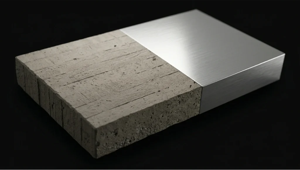
- Range: 0.0 (mirror-polish) to 1.0 (fully diffuse); for architectural concrete, calibrated range is 0.72–0.88; for polished stone, 0.12–0.28
- Do not confuse with Glossiness (inverse value) in legacy V-Ray spec/gloss workflows — confirm workflow before import
- Micro-variation: overlay procedural noise at 2–5% opacity to simulate real surface inconsistency, preventing “CG flat” roughness reads
Shader Spec 4 — Metalness Map
- Color space: Linear
- Binary by physics: values are either 0.0 (dielectric, non-metal) or 1.0 (conductor, metal) — intermediate values apply only to deliberately degraded or oxidized transition zones
- Combined pack option: pack Metalness (R), Roughness (G), Ambient Occlusion (B) into a single RGB texture to reduce memory overhead — standard in Unreal Engine 5 pipelines
Shader Spec 5 — Ambient Occlusion Map
- Color space: Linear
- Bake method: screen-space AO introduces temporal instability in animations; use ray-traced AO baked to texture for static architecture
- Ray count: minimum 256 rays at 1m max distance for exterior crevices; 512 rays at 0.3m max distance for interior joinery and material insets
- Blend mode: Multiply at 50–80% opacity over albedo in composite; never bake AO into the albedo map itself — loss of re-lighting flexibility
Shader Spec 6 — Displacement / Height Map
- Color space: Linear
- Bit depth: 16-bit mandatory — 8-bit displacement produces visible stepping on low-frequency surface relief
- Subdivision requirement: Arnold’s adaptive subdivision (
subdiv_type: catclark,subdiv_iterations: 3–5) at render time; V-Ray equivalent: VRayDisplacementMod at 2cm world-space precision - Avoid micro-displacement on background geometry; apply only to surfaces within 2m of primary camera position to preserve render budget
Phase 3 — Shader Network Assembly
Arnold Standard Surface — Recommended Parameters for Architectural Materials
aiStandardSurface {
  base:             1.0
  base_color:       [albedo_map] sRGB
  specular:         1.0
  specular_roughness: [roughness_map] linear
  specular_IOR:     1.52  // float glass default
  coat:             0.0–1.0  // for lacquered or wet surfaces
  normal:           [normal_map] tangent space
  displacement:     [height_map] linear, midpoint 0.5
}
V-Ray VRayMtl — Equivalent Configuration
VRayMtl {
  diffuse_color:    [albedo_map] sRGB
  reflect_color:    white (1,1,1)
  reflect_glossiness: [1.0 - roughness_map]  // inverted
  fresnel:          enabled, IOR 1.52
  bump_map:         [normal_map] NormalMap type, tangent space
  displacement:     VRayDisplacementMod, 2cm precision, 16-bit heightmap
}
Comparative Analysis: Nuvira Vs. Industry Standard
Arnold vs. V-Ray — Architectural Visualization Context
The render engine debate is frequently argued on speed. That is the wrong axis for photorealistic architectural work. The correct axes are material predictability, GI stability, and shader portability.
| Parameter | Arnold (Standard Surface) | V-Ray (VRayMtl) |
|---|---|---|
| GI Method | Brute-force path tracing | Path tracing + Irradiance Cache hybrid |
| Shader Portability | MaterialX / OpenPBR (cross-engine) | V-Ray Cosmos ecosystem (proprietary) |
| Normal Map Encoding | OpenGL convention | DirectX convention (Y-invert required) |
| Displacement Precision | Adaptive subdivision (Catmull-Clark) | VRayDisplacementMod, world-space clamp |
| GPU Acceleration | Arnold GPU via OptiX 8 (Arnold 7.3+) | V-Ray GPU, biased + unbiased modes |
| Denoiser | OptiX AI + OIDN | V-Ray Denoiser + Intel OIDN |
The Nuvira Position: Arnold’s unbiased Monte Carlo approach delivers superior material predictability across varied lighting environments — critical when a single asset must read correctly under Rotterdam’s overcast grey-sky conditions and Singapore’s high-contrast equatorial sun at the same specification. V-Ray’s irradiance cache hybrid accelerates interior scenes but introduces GI instability across animation frames without careful parameter locking (light_cache_subdivs: 2000 minimum; retrace_threshold: 2.0). For architects evaluating real-time visualization tools that sit earlier in the production chain, the breakdown of Lumion vs Enscape vs D5 Render provides a complementary engine-selection framework before offline rendering decisions are locked.
Where Industry Standard Pipelines Fail
Most architectural visualization pipelines treat texture mapping as a post-geometry task — something addressed after modeling is complete. This produces three systematic failures:
- UV rework after topology changes — UV coordinates baked to a mesh before it is finalized require complete remapping after every structural edit
- Color space contamination — Linear textures imported without color space metadata flag as sRGB in the renderer, producing blown-out specular reads and washed albedo
- Texel density inconsistency — No scene-wide density standard forces material resolution to vary across assets, visible as blurry-to-sharp transitions at camera cuts
Nuvira’s pipeline addresses all three by treating UV strategy, color space policy, and density standards as pre-production constraints — locked before a single material is authored.
Concept Project Spotlight
Speculative / Internal Concept Study — “Meridian Veil” by Nuvira Space
Project Overview
Location: Tanjong Pagar waterfront district, Singapore
Typology: Mixed-use vertical residential tower, 42 floors, tropical high-density urban context
Vision: A facade system that performs differently under Singapore’s two dominant light conditions — overcast monsoon diffusion and direct equatorial high-noon specular loading — using texture-mapped shader stacks rather than physical louver systems.
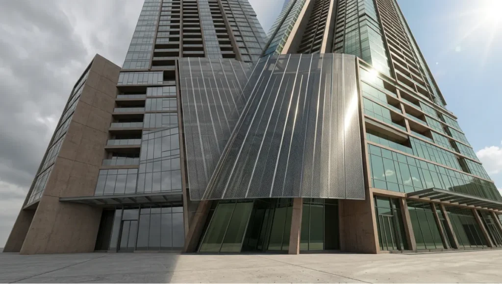
Singapore’s latitude (1.35°N) produces a solar altitude angle exceeding 80° at midday, generating specular highlights on vertical glass and polished cladding at intensities that overwhelm standard HDRI-based lighting rigs. Most archviz pipelines either clip those highlights or underexpose the mid-tones. Meridian Veil was developed as a shader study to solve both.
Design Levers Applied
Facade Material System — Shader Stack
Layer 1 — Structural Concrete Core
- Albedo: custom photogrammetry scan of Singapore-regional laterite-tinted concrete, 4K, 16-bit — for a technical breakdown of how photogrammetry capture integrates into architectural pipelines, see photogrammetry in architecture
- Roughness range: 0.76–0.84 (rain-weathered zone) / 0.61–0.68 (sheltered zone)
- Normal: 16-bit tangent-space bake from 3mm surface scan geometry
- Displacement: 8mm peak-to-trough relief, Catmull-Clark subdivision level 4
Layer 2 — Perforated Anodized Aluminum Screen
- Metalness: 1.0 (pure conductor)
- Roughness: 0.18 (mill-finish anodize) — directional roughness via anisotropy node at 0.4, rotated to vertical axis to simulate extrusion grain
- IOR: 1.0 (metal Fresnel handled through metalness workflow, not IOR input)
- UV: tri-planar projection at 1:1 world scale; no UV unwrap required for repeating screen geometry
Layer 3 — High-Transmission Glazing
- Base color: near-white with 0.04 green tint (R:0.96, G:1.0, B:0.95) at 0.02 opacity — simulates selective solar coating
- Transmission: 0.92
- Thin-wall mode: enabled (single-face glass geometry)
- IOR: 1.517 (soda-lime glass specification)
- Roughness: 0.0 at centerfield, 0.08 at edges (simulating condensation micro-texture baked to edge mask)
Lighting Rig — Singapore Equatorial Specification
- Sun system: physical sun at latitude 1.35°N, azimuth 180° (due south), altitude 82° (June solstice noon)
- Sky model: Hosek-Wilkie physical sky, turbidity 3.2 (tropical haze)
- Supplementary HDRI: 32-bit Singapore CBD skyline panorama, rotation-matched to sun azimuth
- GI: Arnold brute-force path tracing, AA samples 8, diffuse samples 4, specular samples 4
Post-Production — AOV Composite Stack
Final Beauty = Diffuse + Specular + Transmission + Coat + Emission
Grading:    ACES AP0 → sRGB transform
Color temp: 5500K (noon daylight)
Contrast:   S-curve, shadow lift +8, highlight rolloff at 96% luminance
Transferable Takeaway
The Meridian Veil study produced one high-value finding applicable to any photorealistic pipeline: roughness is a climate variable, not a material constant. A single material in a real building reads differently under Singapore’s direct specular load versus Rotterdam’s diffuse sky — and your shader must account for both if the visualization is to function as evidence rather than illustration. Build roughness as a range (min–max), not a fixed value, and expose that range as a parameter at the top of your shader network for environment-specific adjustment without re-authoring the material.
Intellectual Honesty: Hardware Check
Photorealistic texture mapping at the specification levels described in this guide carries hard hardware requirements. There is no pipeline optimization that substitutes for VRAM when handling 16-bit 4K texture stacks across a full-scene material library.
Minimum viable specification for this workflow:
| Component | Minimum | Recommended |
|---|---|---|
| GPU VRAM | 12GB (NVIDIA RTX 3080) | 24GB (NVIDIA RTX 4090) |
| System RAM | 64GB DDR4 | 128GB DDR5 |
| CPU (offline renders) | 16-core (Ryzen 9 5950X) | 32-core (Threadripper PRO 5965WX) |
| Storage I/O | NVMe SSD, 3,500 MB/s read | NVMe RAID-0, 7,000+ MB/s read |
| OS | Windows 10 64-bit | Windows 11 64-bit |
Where pipelines fail on underpowered hardware:
- Texture streaming failures under V-Ray GPU when VRAM is saturated by 4K stacks — the render silently degrades to 2K without warning
- Arnold CPU render times for 16-bit displacement geometry at Catmull-Clark level 4 exceed 45 minutes per frame on 8-core systems — budget accordingly
- 16-bit normal map processing requires linear color space enforcement; hardware display gamma can silently convert linear assets if ICC profiles are misconfigured at the OS level
If your hardware sits below the minimum spec, the practical correction is not to reduce texture quality — it is to reduce the number of simultaneous hero materials and manage texture budgets per render layer rather than per scene.
2030 Future Projection
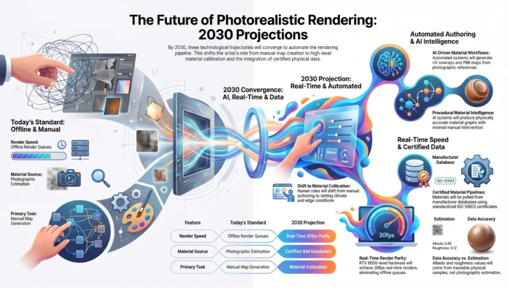
Three trajectories are converging that will fundamentally change how texture mapping photorealistic renders functions as a discipline by 2030.
2030 Projections
1. Procedural Material Intelligence AI-driven material systems (Substance 3D’s generative workflows, Adobe’s Project Neo) are already producing physically accurate material graphs from photographic reference with minimal manual authoring. By 2030, the UV unwrap and PBR map generation pipeline will be partially automated for standard material classes — concrete, glass, metal, stone. The human authorship role shifts from map generation to material calibration: setting climate range parameters, specifying IOR from material certificates, and authoring the edge conditions that automated systems cannot infer from photographs.
2. Real-Time Parity with Offline Unreal Engine 5’s Lumen global illumination and Nanite virtualized geometry have already closed 70–80% of the perceptual gap between real-time preview and offline render output for architectural visualization. By 2030, GPU hardware at RTX 6000-generation levels will render scenes at the material specification described in this guide in real time at 30fps — eliminating the offline render queue entirely for standard deliverables. The constraint shifts from render time to material authoring time.
3. Material Certification Pipelines Building Information Modeling integration is pushing visualization pipelines toward certified material data — manufacturers providing IOR, roughness, and spectral reflectance values as standardized digital material certificates (ISO 10303 STEP files). The AIA Technology in Architectural Practice knowledge community has been documenting this shift in how firms integrate digital material specifications into BIM-to-render pipelines. By 2030, your albedo and roughness values will not come from photographic estimation — they will be pulled from a material specification database, traceable to a physical sample.
Secret Techniques: Advanced User Guide
These are not documented in standard software manuals. They are operational decisions that senior visualization artists apply silently.
Technique 1 — The Roughness Weather Pass After completing your base shader stack, create a second roughness map that adds 0.08–0.12 to all values in areas exposed to precipitation (horizontal surfaces, sill edges, unprotected panels). Apply this second map via a mask driven by world-space Y-axis gradient (surfaces facing upward weighted higher). The result: materials that read as weather-aged without visible texture repetition or staining maps.
Technique 2 — IOR-Driven Fresnel Override Default fresnel behavior in Arnold Standard Surface (IOR 1.5) reads correctly for glass but produces slightly over-reflective behavior for architectural stone and concrete (correct IOR range: 1.4–1.6 for stone; 1.5–1.6 for concrete). Pull the IOR input from a texture map (sampled from a greyscale mask) rather than a fixed value — IOR variation across a stone surface creates the subtle reflectivity gradients that separate photogrammetry-quality materials from synthetic ones.
Technique 3 — Normal Map Blending (Detail + Base) Do not rely on a single normal map for large architectural surfaces. Layer two normal maps in your shader:
- Base normal: large-scale surface relief (form variation, pour lines in concrete, tooling marks in stone) — tiled at 1:1 world scale
- Detail normal: micro-surface grain (surface texture at fingertip proximity) — tiled at 8–16x
- Blend: Arnold’s normal_map node supports blend weight; set detail at 0.3–0.5 weight relative to base
Technique 4 — ACES-First Color Grading Never grade in sRGB. Set your renderer output to ACEScg (AP1) and convert to sRGB only at the final export step. Grading in ACES preserves specular highlight detail in the 100–10,000 nit range that sRGB clips at 100 nits — the difference between a believable equatorial noon render and an overexposed one.
Technique 5 — Baked vs. Ray-Traced AO Decision Protocol Use baked AO when: the scene is static, camera moves are predefined, and render budget is constrained. Use ray-traced AO when: the scene involves animated elements (moving sun, opening doors, changing furniture), the camera explores the space dynamically, or client review requires interactive viewport quality. Never combine both — baked AO applied to a scene also running ray-traced AO doubles the shadow density in crevices and produces a dirty, over-darkened read.
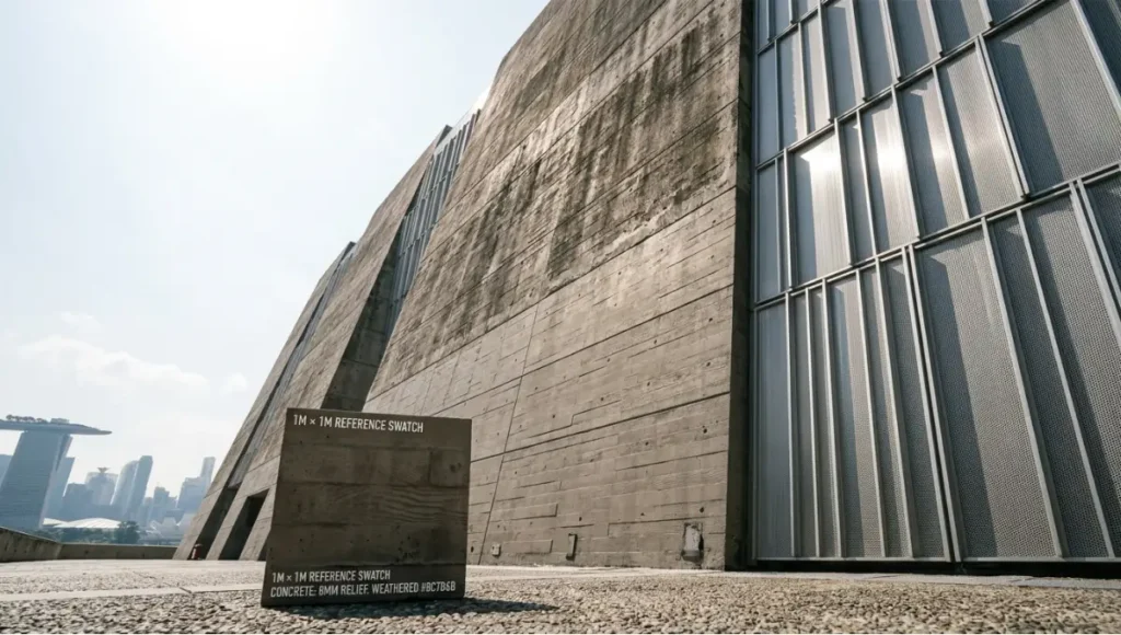
Technique 6 — UV Scale Verification via Real-World Reference Before final render, place a 1m × 1m reference plane in the scene and assign your material. Photograph a physical 1m × 1m sample of the actual material (or source a manufacturer swatch image at documented scale). Compare them at matching camera distance. If the digital tile frequency does not match the physical sample, your UV scale is wrong — not your roughness, not your normals. Correct the UV tiling value (tiling_u / tiling_v) until they match. This single verification step eliminates the most common cause of “CG” material reads.
Comprehensive Technical FAQ
Frequently Asked Technical Questions
Q: What is the difference between bump maps and normal maps, and which should I use for architectural surfaces?
A: A bump map encodes surface relief as a single greyscale channel — lighter values read as raised, darker as recessed. The renderer approximates surface normals from this gradient. A normal map encodes the actual X, Y, Z direction of each surface normal as RGB color data, providing far more directional accuracy. For architectural visualization, always use normal maps on hero assets — bump maps introduce directional artifacts under oblique lighting that are immediately visible on flat, large surfaces like facades and floors. Reserve bump maps for background assets where render budget is constrained.
Q: Why does my material look correct in the Substance Painter viewport but washed out in Arnold or V-Ray?
A: This is a color space mismatch. Substance Painter’s viewport uses an approximated environment with Iray’s physically based preview — not the same color pipeline as your offline renderer.
- Confirm: Substance Painter export preset matches your target renderer (Arnold or V-Ray presets are built-in)
- Confirm: All linear textures (normal, roughness, metalness, AO, displacement) are imported with
Linearcolor space in your renderer, notsRGB - Confirm: Your renderer color profile is set to ACEScg or sRGB, not gamma 2.2 legacy mode
- Symptom check: washed albedo = sRGB map imported as Linear; blown specular = roughness map imported as sRGB instead of Linear
Q: How do I prevent visible tiling on large architectural surfaces like floor slabs and facade panels?
A:
- Apply a stochastic tiling node (Arnold:
aiCellNoiseoraiNoisedriving UV offset per-tile; Blender: Random per-island UV node) - Layer a secondary macro-variation texture at 4–8x scale of the base tile — slight color and roughness variation breaks repetition visually without requiring unique UVs
- Use RizomUV’s trim-sheet workflow for repetitive architectural elements — maps a library of unique surface sections to a shared trim atlas, eliminating tile repetition entirely
- Overlap UV islands intentionally at different rotations — texture repetition reads as tiling when orientation repeats; rotating alternate islands by 90° or 180° disrupts the pattern
Q: What is the correct displacement subdivision level, and how does it affect render time?
A:
- Arnold Catmull-Clark level 1 = 4× original polygon count; level 2 = 16×; level 3 = 64×; level 4 = 256×
- For 8mm peak-to-trough displacement on a 50m facade panel at 2m camera distance: level 3 is sufficient (tessellation produces approximately 3mm world-space triangles, below displacement feature size)
- Render time impact: each additional subdivision level approximately doubles render time for displacement-heavy geometry
- Rule of thumb: set subdivision level such that tessellated triangle size is ≤ 50% of the smallest displacement feature you need to resolve
Q: PBR metallic/roughness vs. specular/glossiness — which workflow should I use?
A:
- Metallic/roughness: simpler channel structure, native to Unreal Engine, Blender Cycles, Arnold Standard Surface. Preferred for new projects.
- Specular/glossiness: legacy workflow in V-Ray VRayMtl and older Substance exports. Glossiness is the inverse of roughness (Gloss = 1.0 − Rough). If importing legacy assets, convert rather than re-author: invert the glossiness channel to produce a roughness map.
- Cross-renderer note: V-Ray’s metallic/roughness VRayMtl (introduced in V-Ray 6) now natively matches Arnold Standard Surface parameter ranges — use this for new V-Ray projects to maximize shader portability.
Q: How do I verify texel density is consistent across a full architectural scene?
A: Use the engine’s UV density visualization mode:
- 3ds Max + V-Ray: Apply Checker map at 1.0 UV tiling to all materials; consistent checker square size = consistent texel density
- Blender:
Texture Paint → Checker Textureoverlay at 10.24 texels/cm calibration target - Unreal Engine 5:
Optimization Viewmode → Texel Density— color codes surfaces from green (target density) to red (over-density) to blue (under-density)
Target variance: ±10% texel density across primary surfaces within the same camera field. Greater variance reads as inconsistent material “resolution weight” — certain surfaces appear sharper than physically plausible given the scene’s camera distance.
Build the Render That Reads as Real
The gap between a render that impresses and a render that convinces is measured in shader parameters, not artistic intention. Texture mapping photorealistic renders is not a style choice — it is a technical infrastructure that either supports or undermines every other decision in your pipeline. The 6 shader specs outlined in this guide are not creative starting points. They are calibrated specifications derived from energy conservation physics, color science, and architectural surface behavior under documented lighting conditions.
Apply the UV strategy before topology is finalized. Lock your color space policy before a single map is imported. Set your texel density standard before the first shader node is connected. Then build from the albedo up — map by map, channel by channel — and validate against a physical reference before the camera moves.
When that is done correctly, the render does not need to announce itself. It reads.
© Nuvira Space. All rights reserved. | THE VISUAL LAB Series | All specifications cited are based on Arnold Standard Surface technical documentation (Autodesk Arnold 7.4), V-Ray Material documentation (Chaos Group V-Ray 6), Physically Based Rendering: From Theory to Implementation (Pharr, Jakob, Humphreys — 4th Edition), and Adobe Substance 3D PBR export guidelines. The Meridian Veil is a speculative internal concept study and does not represent a completed project.