
Table of Contents
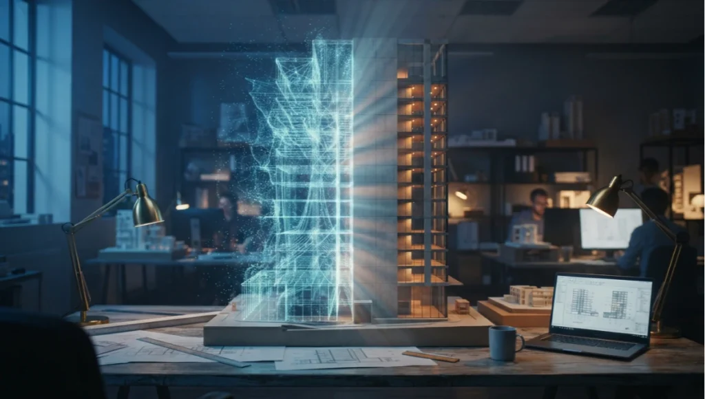
NeRF Architectural Visualization 2D to 3D has moved from a research curiosity into a working pipeline decision inside production studios. Where a decade ago converting a flat elevation or a stack of site photographs into a navigable spatial model meant weeks of manual photogrammetry cleanup, neural radiance fields now compress that timeline into hours — provided the studio understands where the technique still needs a human hand on the wheel. This guide is written for the artist who has already rendered a thousand interiors and wants to know exactly what changes, technically, when the pipeline shifts from polygon-first thinking to field-based reconstruction.
The shift is not cosmetic. It changes what a “site visit” produces, what a junior artist spends their first week learning, and what a client sees in the first review meeting. Studios that have made the transition report that the biggest adjustment is not the software itself but the sequencing of decisions — capture discipline now happens before any creative direction is set, rather than after a scan has already been delivered by a third-party surveyor. That reordering is the practical subject of everything that follows.
Nuvira Perspective
At Nuvira Space, we treat real-time engines and neural reconstruction not as competing toolchains but as two halves of the same argument: that architectural intent and architectural reality should be separated by hours, not months. Human-machine synthesis — the practice of letting a trained artist steer a machine-learned representation rather than hand-author every vertex — is the operational core of how we now bridge concept and constructed space. When a studio can reconstruct a site condition from a phone-shot walkthrough and layer a proposed intervention directly into that reconstruction, the feedback loop between designer and client compresses from a presentation cycle into a working session.
This is not a claim about novelty for its own sake. It is a claim about where visual value is actually created in a rendering pipeline — and increasingly, that value sits upstream of the render, in how faithfully the captured environment matches the light, material, and scale of the real site.
The profession’s own institutions are tracking the same shift: the AIA AI Task Force has flagged real-time rendering and visualization as one of the areas where machine-assisted workflows are moving fastest from experimental to standard practice.
What that institutional attention misses, from a floor-level production standpoint, is how much of the gain is procedural rather than algorithmic. The network architecture behind a modern radiance field trainer has been broadly stable for several release cycles; what has changed is the surrounding discipline — capture protocol, pose verification, hybrid mesh-and-splat scene assembly — that turns a research-grade reconstruction into something a client-facing render can be built on top of. Treat the model as the least interesting part of the stack and the capture-to-composite pipeline as the part actually worth mastering.
Step-by-Step Workflow & Features
The workflow below assumes a mid-sized commercial or residential visualization brief where a site survey already exists in some form — video walkthrough, drone pass, or DSLR bracket sequence.
Stage 0 — Pre-Production Planning
Before anyone picks up a camera, the studio needs to decide what the reconstruction is actually for. A radiance field intended purely as a background plate for a design-intervention render has different tolerances than one intended to carry dimensional accuracy for a client walkthrough.
- Define the hero surfaces up front — the walls, floors, or façades the design intervention will directly replace — since these need the highest-resolution capture pass.
- Decide the delivery format (static render, real-time walkthrough, VR review) before capture, since it determines whether you need a fully retopologized mesh or a splat-only environment layer is sufficient.
- Confirm site access windows against weather — a single overcast-light capture window is worth more than three sunny ones for radiance field consistency.
Stage 1 — Capture Discipline
Neural radiance field quality is bottlenecked by capture discipline more than by network architecture. Before any 2D-to-3D conversion begins:
- Maintain 60–80% frame overlap between consecutive captures; below 50% overlap, pose estimation drifts and produces floating artifacts.
- Shoot in diffused, overcast light where possible — hard shadows bake false geometry into the radiance field.
- Fix exposure and white balance manually; auto-exposure shifts between frames corrupt the color-consistency assumption the model relies on.
- Capture a full orbit at three height bands (knee, eye, overhead) for any feature intended as a hero shot.
Stage 2 — Structure-from-Motion Pre-Pass
Run a COLMAP or equivalent SfM pass before handing frames to the radiance field trainer. This produces the sparse point cloud and camera pose file the network needs as an initialization prior.
- Target reprojection error under 1.0 pixel across the pose set.
- Discard any camera with fewer than 40 matched features — these poses are unreliable and will introduce ghosting.
- Export in the COLMAP text format most training frameworks (Instant-NGP, Nerfstudio) expect natively.
If the SfM pass fails to converge on a subset of frames — a common issue in long hallway captures with repetitive geometry — split the capture into overlapping segments and run pose estimation separately on each before merging. Attempting to force a single global bundle adjustment on a repetitive corridor is the single most common cause of a failed reconstruction at this stage, and it is far cheaper to catch here than after 30,000 training iterations.
Stage 3 — Field Training & Mesh Extraction
With poses locked, train the radiance field itself, then extract a usable mesh for downstream engine work.
Training parameters worth tuning
- Hash-grid resolution: 16–19 levels for architectural interiors; lower levels blur fine trim detail.
- Density regularization weight: raise it for glass and mirrored surfaces, which otherwise produce floating density artifacts.
- Training steps: 20,000–35,000 iterations is typically sufficient for a single-room capture at production quality.
Mesh extraction
- Marching cubes resolution of 512³ minimum for anything intended as a walkable base mesh.
- Poisson surface reconstruction as a cleanup pass to close small capture gaps before retopology.
Expect the raw extracted mesh to carry noise on any surface that was under-captured — stairwells, tight closets, ceiling corners. Rather than manually sculpting these regions, re-run a targeted capture pass on just the problem area and re-train a small local radiance field, then stitch the two meshes at a clean seam. This is faster and more accurate than hand-modeling the gap from reference photos, and it keeps the entire asset traceable back to real capture data.
Stage 4 — Engine Integration
The extracted mesh, plus a baked or Gaussian-splat representation of the far-field environment, is brought into the real-time engine — most commonly Unreal Engine 5 on current projects — for lighting and material work.
- Use Gaussian splatting for background/environment layers where geometry accuracy matters less than lighting fidelity.
- Retopologize only the surfaces the design intervention will touch — walls being demolished, floors being replaced — leave the rest as reconstructed mesh.
- Global illumination: switch to a hardware ray-traced GI solution once the scene is inside the engine; radiance-field lighting is baked and will not respond correctly to new light sources you add for the design proposal.
Stage 5 — Post-Production
- Composite the reconstructed base with the CG design intervention using a depth-matched AOV pass, not a flat 2D overlay.
- Match the color grade of the CG elements to the captured base using a LUT extracted from the original photography, not a generic architectural grade.
- Add controlled chromatic aberration and lens distortion matching the original capture lens — this is the detail that most often gives away a composite.
A camera-lens-aware compositing pass matters more here than in a purely CG render, because the reconstructed base already carries the optical signature of a specific real lens. Skipping this step is the fastest way to produce a technically accurate composite that still reads as artificial to a trained eye — the CG elements sit too clean against a base that has real-world lens characteristics baked in.
Comparative Analysis: Nuvira Vs. Industry Standard
Most studios still run photogrammetry-to-mesh as the default 2D-to-3D pipeline. It is a mature process, but it optimizes for geometric accuracy at the expense of everything a radiance-field approach captures for free.
Where photogrammetry still wins
- Hard-surface dimensional accuracy for as-built documentation — photogrammetry mesh tolerances are better understood and easier to QA.
- Point-cloud interoperability with existing BIM and CAD pipelines.
- Predictable processing on lower-end hardware without a dedicated GPU trainer.
Where the Nuvira NeRF-based pipeline wins
- View-dependent materials — glass, brushed metal, water — reconstruct with correct specular behavior instead of the flat, baked-albedo look photogrammetry produces on reflective surfaces.
- Turnaround: a 200-frame capture trains to a usable field in 15–25 minutes on a single high-end GPU, versus multi-hour dense-cloud processing for an equivalent photogrammetry mesh.
- Volumetric detail — foliage, fabric, complex railings — survives reconstruction instead of collapsing into a low-poly approximation.
- Lighting fidelity in mixed interior/exterior shots — a radiance field captures the actual interplay of daylight through glazing at the moment of capture, which a photogrammetry mesh has to fake with a generic HDRI later.
- Lower crew overhead — a single operator with a handheld rig or drone can complete a capture that would otherwise require a dedicated laser-scanning technician.
None of this makes photogrammetry obsolete. The two approaches increasingly coexist within the same project: a photogrammetry-derived point cloud for dimensional QA against the architectural drawing set, and a radiance-field reconstruction for the client-facing visual asset. Studios that pick one to the total exclusion of the other are usually leaving value on the table in one direction or the other.
Case Study Context: Rotterdam
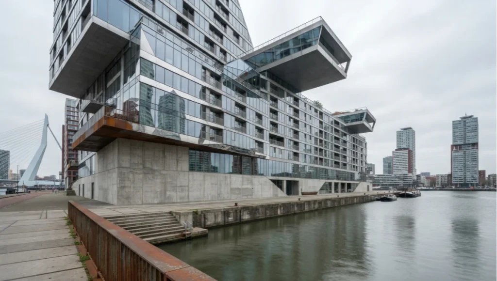
A recent internal test capture along Rotterdam’s Kop van Zuid waterfront illustrates the gap concretely. A 340-frame drone-and-handheld hybrid capture of a mixed-use block — heavy on glazing, water reflections, and cantilevered steel — reconstructed via radiance field in under 30 minutes with specular water and glass intact. The equivalent dense photogrammetry pass on the same capture set required roughly four hours of processing and produced visibly flattened reflections on every glazed façade, which then had to be manually re-textured in post. The time saved was not marginal; it changed whether the studio could turn the concept around for a same-day client review.
The Rotterdam test also surfaced a secondary benefit that is easy to overlook in a pure speed comparison: because the radiance field preserved the actual reflected sky and neighboring building color in the water and glazing, the composited design elements needed almost no manual color correction to sit convincingly within the scene. On the photogrammetry pass, matching the flattened, re-textured water back to a believable reflection took a colorist most of an afternoon. That is a cost most pipeline comparisons never line-item, because it happens downstream of the modeling step most studios use to benchmark the two approaches against each other.
Concept Project Spotlight
Speculative / Internal Concept Study — “Kade Verlicht” by Nuvira Space
Project Overview
- Location: Rotterdam, Netherlands — Kop van Zuid waterfront
- Typology: Mixed-use residential-over-retail infill block
- Vision: Test whether a radiance-field reconstruction of an existing waterfront block could carry a full massing-and-façade study without a traditional laser scan
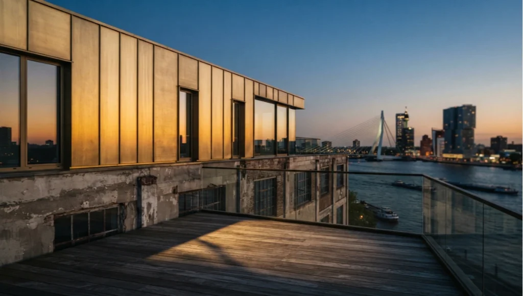
The site was chosen specifically because it stress-tests the weakest point of earlier reconstruction techniques: dense glazing directly adjacent to open water, under variable overcast light. If the pipeline could hold up here, the internal team reasoned, it would hold up on the large majority of waterfront and high-glazing briefs the studio receives.
Design Levers Applied
Capture and reconstruction
- Hybrid drone orbit + ground-level handheld pass, 340 frames total
- Radiance field trained at 18 hash-grid levels, 28,000 iterations
- Gaussian splat layer retained for the water and distant skyline; hero façade retopologized to a clean quad mesh
Design intervention
- Proposed façade re-cladding modeled as a discrete CG layer, composited with depth-matched AOVs against the reconstructed base
- Massing study for a rooftop addition tested directly inside the reconstructed volumetric context rather than a blank-site model
The choice to retain the Gaussian splat layer for the water and skyline rather than converting the entire scene to mesh was deliberate: converting reflective water to a textured mesh plane would have required a hand-authored reflection setup that never quite matches captured reality, whereas the splat layer already encodes the correct view-dependent reflection behavior directly from the source photography. The team estimated this decision alone saved roughly two days of manual water-shader tuning that would otherwise have been needed to match the reference photography.
Transferable takeaway
The lesson that generalizes beyond this one site: reconstruction quality on reflective, waterfront-adjacent materials is the single best predictor of whether a radiance-field pipeline will outperform photogrammetry on a given brief. If the site brief is dominated by matte, diffuse surfaces, the advantage narrows considerably.
A practical screening question for any new brief, then, is not how large the site is but how much of the visible surface area is specular, reflective, or fine-volumetric — glazing, water, foliage, fabric, brushed metal. Briefs that score high on that count are strong candidates for a radiance-field-first pipeline; briefs dominated by painted drywall and matte concrete may not justify the additional capture discipline the technique demands.
Intellectual Honesty: Hardware Check
None of the above is free. A radiance-field training pass that completes in 20 minutes on a 24GB workstation GPU can take considerably longer, or fail outright on memory, on a laptop-class card — see our current GPU benchmarks for rendering for hardware-specific guidance. Before committing a client timeline to this pipeline, confirm:
- Minimum 16GB VRAM for interior-scale captures; 24GB or more for anything with more than 300 frames or 4K source imagery.
- A capture crew comfortable with manual exposure and overlap discipline — the pipeline’s speed advantage evaporates if the capture has to be reshot.
- Storage overhead: raw frame sets plus checkpoint files for a single mid-size capture routinely exceed 40GB before any mesh export.
- Network bandwidth if training on a cloud instance — a 40GB raw capture set uploaded over a slow studio connection can erase the entire time advantage of the faster training step.
- A render farm or workstation queue that can absorb an unplanned re-train — first-pass training runs fail to converge cleanly often enough that the schedule should assume at least one retrain per capture.
None of this is disqualifying, but it is a real cost that a purely software-focused comparison tends to omit. Studios evaluating whether to adopt this pipeline should budget the hardware and crew-training cost against the time saved on capture-to-delivery, not against the training-step speed alone — the honest comparison is pipeline-to-pipeline, not GPU-to-GPU.
2030 Future Projection
Local chapters are already building shared infrastructure around this — the AIA San Francisco Technology in Architectural Practice group regularly convenes computational designers to compare real-time rendering and reconstruction workflows across firms, which is a useful signal of where the practice-wide baseline is heading.
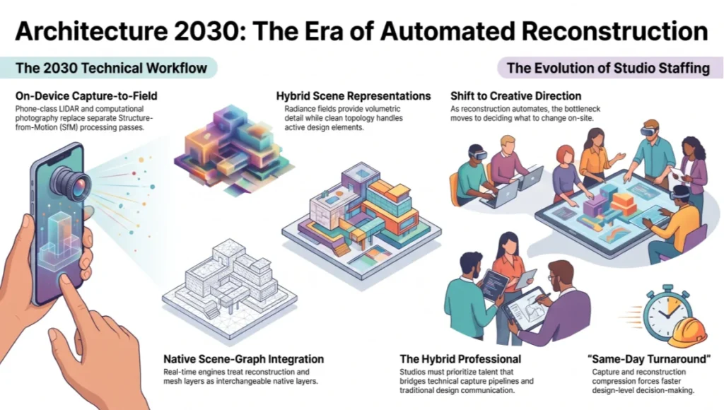
By 2030, expect the capture-to-field step to move largely on-device — phone-class LiDAR and computational photography already produce usable initialization poses without a separate SfM pass, and that trend will continue closing the gap between site visit and working 3D asset. The likely shift is not that radiance fields replace mesh-based pipelines outright, but that the two representations become interchangeable layers within the same scene file: reconstructed volumetric detail for anything the design isn’t touching, clean topology for anything it is. Real-time engines will increasingly treat this as a native scene-graph distinction rather than a manual conversion step.
The second-order effect worth watching is on staffing rather than software. As capture and reconstruction compress toward same-day turnaround, the bottleneck in a studio’s pipeline shifts back toward creative direction and design judgment — deciding what to change about a reconstructed site, not how to reconstruct it. Studios that invest now in artists who understand both the technical capture pipeline and traditional design communication will be better positioned than studios betting entirely on either skill set alone.
Secret Techniques: Advanced User Guide
These are workflow adjustments that rarely appear in default tool documentation but consistently separate a production-ready reconstruction from a portfolio demo.
- Train two radiance fields at different exposure brackets and blend the density fields — this recovers detail in both deep shadow and blown-out glazing that a single-exposure capture loses.
- Use a low-weight depth-supervision loss from a sparse LiDAR pass (even a phone LiDAR scan) to stabilize scale on featureless surfaces like plain drywall, where photometric-only training drifts.
- For interiors with mirrors, mask the mirror region out of the training set entirely and reconstruct it separately as a planar reflection plane in-engine — radiance fields consistently misinterpret mirror content as duplicate geometry.
- When extracting a mesh for retopology, extract at a higher marching-cubes resolution than you need, then decimate — extracting directly at low resolution loses edge definition that decimation alone cannot restore.
- Bake a secondary, lower-resolution radiance field trained on a night or dusk capture pass specifically for interior-lighting studies — daylight-trained fields do not extrapolate artificial lighting scenarios reliably.
- When a client requests a mid-project material change, avoid re-training the entire field. Isolate the affected surface region using a bounding-box mask and re-train only that sub-volume against a fresh partial capture; this cuts iteration time from hours back down to minutes.
Comprehensive Technical FAQ
Q: Does a radiance-field pipeline replace laser scanning for as-built documentation?
A: Not for anything requiring certified dimensional tolerance. Radiance fields are a visualization and design-communication tool; laser scanning remains the standard where measurements carry legal or construction weight.
Q: What frame count is realistic for a single-room capture?
A: 120–200 frames for a room under 40 square meters is typically sufficient. Larger open-plan spaces need proportionally more.
- Small room (under 20m²): 80–120 frames
- Medium room (20–40m²): 120–200 frames
- Open-plan / multi-room (40m²+): 250–400 frames, captured in overlapping passes
Q: Can this run without a dedicated GPU?
A: Training will run on cloud GPU instances if local hardware is insufficient, at the cost of upload time for the raw capture set.
Q: How does lighting from the design proposal interact with the reconstructed base?
A: It does not, automatically. Radiance-field lighting is baked from the original capture. Any new light source introduced for the proposed design must be added and rendered inside the real-time engine after mesh extraction, not inside the field itself.
Q: How long does the entire pipeline take, start to finish?
A: For a single-room interior with a same-day capture, expect roughly: 1–2 hours capture, 20–40 minutes training, 30–60 minutes mesh extraction and cleanup, and a variable amount of engine and post-production time depending on the design intervention’s complexity. A full same-day turnaround from site visit to first-draft composite is realistic for most interior briefs.
Q: What is the most common quality failure and how is it diagnosed?
A: Floating density artifacts — faint cloud-like geometry hanging in open space — are the most common failure, almost always traceable to insufficient frame overlap or inconsistent exposure during capture. The fix is at the capture stage, not the training stage; increasing regularization weight can mask the symptom but rarely resolves it cleanly.
Q: Can radiance-field reconstructions be handed to a structural or MEP consultant?
A: Not directly. The mesh extracted from a radiance field is a visual approximation, not a survey-grade deliverable, and should not be used as the geometric basis for structural or mechanical coordination without independent verification.
Q: How should a studio price this differently from a traditional visualization job?
A: The honest answer is that capture and reconstruction time drops sharply, but design, composite, and review time does not shrink proportionally — most of the labor in a visualization brief was never in the modeling step to begin with. Studios that price purely on the old modeling-hours basis tend to under-charge once this pipeline is adopted, since the client-facing value (turnaround speed, review iterations, material fidelity) goes up even as raw hours logged on reconstruction go down.
Talk to the Nuvira Visual Lab
If your studio is still budgeting weeks for site-to-model conversion, the workflow above is worth a pilot run on your next brief. Bring us one capture set and we’ll show you the reconstructed base, the extracted mesh, and the composited design layer side by side against your current pipeline’s output.
There is no obligation attached to the pilot, and no requirement to commit to a full pipeline switch based on a single project. The point is simply to put a real capture set through both workflows and let the studio’s own review process — not a vendor’s marketing claim — decide which asset communicates the design more clearly to the client. Bring your hardest case: heavy glazing, water, or a tight interior with awkward light. Those are the briefs where the difference is easiest to see and hardest to fake.
© Nuvira Space. All rights reserved. | THE VISUAL LAB Series | All specifications cited are based on internal Nuvira Space testing. The "Kade Verlicht" project is a speculative internal concept study and does not represent a completed project.
1 thought on “NeRF Architectural Visualization 2D to 3D Explained”