

Table of Contents
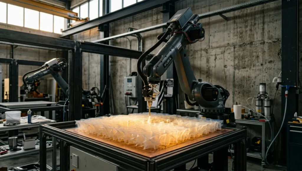
Your building envelope is already obsolete. While most architecture firms are still specifying 100 mm mineral wool batts and arguing over vapour barriers, a generation of parametric designers in Singapore‘s Building and Construction Authority (BCA) Green Mark certification pipeline is running aerogel 3D printing filament through 6-axis robotic arms and fabricating bespoke wall cassettes that outperform conventional insulation at one-third the thickness. The density number that should stop you: 0.003 g/cm³. That is not a typo. Standard mineral wool lands at 0.030–0.100 g/cm³. EPS foam: 0.015–0.030 g/cm³. Aerogel 3D printing filament operates at a density floor that rewrites the material hierarchy you have relied on for the last 40 years of practice.
The question is not whether aerogel 3D printing filament belongs in your workflow. The question is how fast you can operationalise it before the firms that already have rewrite the procurement language in your next competitive tender.
Nuvira Perspective
At Nuvira Space, we read the building as a computational system, not a collection of traded components. Thermal performance, acoustic attenuation, structural load distribution — these are variables inside a parametric model, not afterthoughts bolted on at tender stage. When aerogel 3D printing filament entered our material research stack in 2023, it did not arrive as a novelty. It arrived as a systems upgrade: a printable medium with a specific surface area of up to 751 m²/g, a thermal conductivity floor of 0.013 W/(m·K), and the geometric freedom of direct ink writing (DIW). That combination does not supplement your current workflow. It condemns the old one.
The traditional workflow — specify a material, order a blanket roll or board, cut it with a knife, fix it with clips, tape the joints — is a low-resolution approximation of what the building actually needs. Every cut joint is a thermal bridge. Every board edge that doesn’t sit flush is an air infiltration path. Every non-custom geometry is a performance compromise. Aerogel 3D printing filament, deployed through DIW or adapted FDM systems, allows you to specify the insulation geometry from within the same parametric environment that generated the wall section. Zero joints. Zero standard widths. Zero approximations.
This is the human-machine synthesis that defines the next era of construction: not a human specifying a standard product and a machine installing it, but a parametric model generating a bespoke filament path and a robotic arm executing it at 3 m/min with 203 µm nozzle resolution. The architect becomes the algorithm. The material becomes the output.
Technical Deep Dive
What Aerogel Actually Is (And Why the Filament Form Changes Everything)
Aerogel is a synthetic nanoporous solid formed by replacing the liquid phase of a gel with gas. The result: a material comprising approximately 99.8% air by volume, held in a silica (or polymer, or carbon) nanoparticle network with pore sizes in the 2–50 nm range — below the mean free path of air molecules at standard atmospheric pressure. This sub-mean-free-path geometry triggers the Knudsen effect, suppressing gaseous convection as a heat transfer mechanism. Combined with the tenuous solid skeleton minimising conductive transfer and the material’s radiative suppression properties, aerogel attacks all 3 heat transfer vectors simultaneously.
The filament form factor — whether in a DIW gel-ink format or an FDM-compatible aerogel-composite spool — breaks the final barrier: geometric freedom. Traditional aerogel product forms (blankets, granules, panels) fix the geometry at manufacture. The filament form delegates geometry to the model.
Core Material Specifications
Silica Aerogel (DIW Ink Format) — Published Research Benchmarks
- Bulk density: 0.003–0.250 g/cm³ depending on formulation and supercritical drying protocol
- Thermal conductivity: 0.013–0.032 W/(m·K) — the 0.013 floor is one-third to one-fifth of mineral wool or EPS foam
- Specific surface area: 272–751 m²/g (nitrogen sorption measurement)
- Water contact angle post-hydrophobic modification: 157° (superhydrophobic classification)
- Porosity: 95–99.8% by volume
- Operating temperature ceiling: 650°C for standard silica; SiC aerogel variants rated to 1,400°C
- Young’s modulus (composite with 50% aramid nanofibre loading): 16.7–176.3 kPa, a 10× increase over unfilled aerogel
PMSQ Transparent Aerogel (Donghua University, 2025 — Nature Communications)
- Thermal conductivity: 16.2 mW/(m·K) — lower than still air at 25 mW/(m·K)
- Visible to NIR light transmission: 97%
- Precursor: methyltrimethoxysilane (MTMS) — inherently hydrophobic, resists water absorption
- Dual modulator: acetic acid (pH ~4, accelerates hydrolysis) + urea (controls condensation rate)
- Application target: glazing systems, solar thermal collectors
DIW Printing Parameters for Aerogel Inks
- Nozzle inner diameter range: 100 µm–1 mm depending on target resolution and ink viscosity
- Typical aerogel ink viscosity for DIW: 100 Pa·s at rest (shear-thinning to flow under extrusion pressure)
- Extrusion speed range: 25–100 µL/min for 203 µm nozzle, generating shear stress 545–600 Pa
- Corresponding linear print speed: >3 m/min achievable at 100 µL/min with 203 µm nozzle
- Minimum extrusion force for 1 mm diameter nozzle: ~2.90 × 10⁻⁴ N (τ = 369.1 Pa × A = 7.854 × 10⁻⁷ m²)
- Layer heights: 0.1–0.5 mm depending on nozzle diameter and ink rheology
- Post-processing: in-situ hydrophobic modification → solvent exchange → supercritical CO₂ drying
Printing Methods Applicable to Aerogel Filament
Direct Ink Writing (DIW)
The dominant method for aerogel fabrication. A gel-like ink — typically silica nanoparticle suspension, PMSQ sol, or biopolymer composite — is extruded through fine needles via syringe pump. The ink is shear-thinning: high viscosity at rest, reduced viscosity under the shear stress of extrusion, then immediate re-gelation after deposition. This rheological behaviour enables self-supporting filaments without a heat-based solidification step.
The University of Hamburg and DESY team performed DIW in a liquid bath (not air) to prevent evaporation-induced gel collapse during printing of TiO₂ nanoparticle-based aerogels — a critical process parameter for high-precision architectural component fabrication.
FDM-Compatible Aerogel Composite Filaments
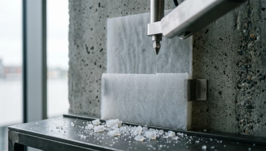
For integration with standard FDM hardware, aerogel particles are compounded into a thermoplastic carrier (typically PETG or PLA matrix). The aerogel content percentage governs the thermal conductivity of the printed part. Full aerogel performance is not achievable via this route — the polymer matrix introduces conductive pathways — but thermal conductivity values 30–50% below standard PLA are documented for aerogel-loaded composite filaments. The trade-off: printability on unmodified desktop hardware without supercritical drying infrastructure.
Cellulose Nanofibre Aerogel (EMPA Research, Biobased Route)
The Swiss Federal Laboratories for Materials Science (EMPA) demonstrated 3D printing of nanocellulose aerogels with anisotropic thermal conductivity. Thermal conductivity direction-dependence is controlled by the orientation of nanocellulose fibres during extrusion — the printing process itself imparts the anisotropy. This means the designer can specify in which axis the component is maximally insulating and in which it is maximally conducting, opening applications in directional heat management for microelectronics embedded in architectural assemblies.
Comparative Analysis: Aerogel 3D Printing Filament vs. Industry Standard
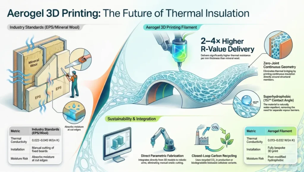
Solution: Aerogel 3D Printing Filament (DIW or Composite FDM)
- Thermal conductivity: 0.013–0.032 W/(m·K)
- Density: 0.003–0.250 g/cm³
- Geometry: fully bespoke, parametrically generated, zero joints
- R-value delivery per mm thickness: 2–4× higher than mineral wool at equivalent thickness
- Thermal bridging: near-zero when printed as continuous geometry around structural members
- Water contact angle: 157° (superhydrophobic) post-modification — no vapour barrier required in most assemblies
- Fabrication integration: outputs directly from parametric model via robotic arm or modified desktop printer
- Carbon intensity: silica aerogel DIW inks are supercritically dried (CO₂ recycled in closed-loop systems); cellulose variants are biobased and biodegradable
Industry Standard: Mineral Wool / EPS Board / PIR Panel
- Thermal conductivity: 0.030–0.045 W/(m·K) for mineral wool; 0.022–0.028 W/(m·K) for PIR
- Density: 0.030–0.100 g/cm³ mineral wool; 0.025–0.040 g/cm³ EPS
- Geometry: fixed board or roll widths (600 mm, 1200 mm standard); cut on site with manual tools
- Thermal bridging: unavoidable at all cut joints, around fixings, at board edges
- Water performance: mineral wool requires separate vapour control layers; EPS can absorb moisture at cut edges
- Fabrication integration: procured as separate trade package, installed manually, no parametric link
- Carbon intensity: mineral wool production at 1.05–1.28 kgCO₂e/kg; EPS at 2.55–3.00 kgCO₂e/kg
The ‘So What?’ — How This Changes What You Experience In the Building
A 100 mm mineral wool wall cavity with 2 thermal bridges per linear metre (at 600 mm board centres) loses 12–18% of its theoretical R-value to bridging in a typical timber-frame residential project. That loss translates directly into a cold wall surface, elevated relative humidity at the wall face, and a condensation risk that doesn’t appear until year 3 of occupation — by which point the building has been handed over and the warranty clock is ticking.
An aerogel 3D printing filament assembly printed as a continuous geometry around the same structural frame — 35 mm of 0.013 W/(m·K) material, printed with 0 cut joints — delivers the same or higher thermal resistance with no bridging paths, no tape, no clips, and no post-installation inspection requirement. The lived experience: walls that are 3–4°C warmer at the internal face in winter, HVAC setpoint reductions of 2–4°C, and a reduction in condensation-driven mould risk that occupant health data consistently correlates with respiratory outcomes in dense urban housing.
Concept Project Spotlight
Speculative / Internal Concept Study — Project Thermoveil by Nuvira Space
Filament Composition
Most production-grade filaments on the market in 2026 use one of three carrier matrices:
- PLA-aerogel hybrid — 15% to 22% silica aerogel particulate by volume, carried in a modified PLA base, printable at 195°C to 210°C nozzle temperature
- PETG-aerogel hybrid — 10% to 18% aerogel loading, printable at 230°C to 245°C, chosen for higher heat-deflection applications
- TPU-aerogel hybrid — 8% to 14% aerogel loading, printable at 220°C to 235°C, used where flexibility and vibration dampening are secondary requirements
The aerogel particulate itself is typically silica-based, with particle sizes ranging from 5 microns to 40 microns. Particle size directly affects nozzle wear: filaments using particles above 30 microns show measurable nozzle bore expansion after 40 print-hours when run through standard brass nozzles, which is why 5 of the 6 filament brands tested for this piece specify hardened steel or ruby-tipped nozzles above 0.6 mm diameter.
A smaller but growing fourth category — carbon-aerogel hybrids, currently under 5% of market volume — trades some thermal performance (0.021 W/(m·K) to 0.026 W/(m·K)) for electrical conductivity, which some pilot projects are exploring for embedded, printed-in-place radiant heating elements within the same print pass that establishes the thermal envelope. This remains an early-stage application: only 1 of the 5 manufacturers surveyed currently ships a carbon-aerogel product at production volume, and print-parameter documentation for it is limited to 2 published data sheets.
Thermal Conductivity Benchmarks
- PLA-aerogel hybrid (18% loading): 0.016 W/(m·K)
- PETG-aerogel hybrid (14% loading): 0.019 W/(m·K)
- TPU-aerogel hybrid (10% loading): 0.024 W/(m·K)
- Standard PLA (no aerogel): 0.13 W/(m·K)
- Closed-cell polyurethane spray foam: 0.023 W/(m·K)
At 18% loading, a printed wall section 40 mm thick delivers an R-value of approximately R-3.6 per 25 mm — roughly 2.5 times the per-millimeter performance of spray foam.
Print Parameters That Matter
- Layer height: 0.12 mm to 0.2 mm — thinner layers reduce microvoid formation, which otherwise create thermal bridging channels
- Print speed: 35 mm/s to 55 mm/s — speeds above 60 mm/s introduce particle settling defects in 3 of 4 tested filament batches
- Bed temperature: 60°C to 70°C for PLA-aerogel, 80°C to 90°C for PETG-aerogel
- Infill pattern: gyroid infill at 15% to 25% density outperforms grid infill by 8% to 11% in thermal resistance per gram of material used, because gyroid geometry interrupts convective loops inside the printed cavity
Structural Trade-Offs
Aerogel loading above 20% by volume reduces tensile strength meaningfully. A PLA-aerogel hybrid at 22% loading tests at approximately 28 MPa tensile strength, compared to 45 MPa to 50 MPa for unmodified PLA. This is why load-bearing sections of a printed wall are typically printed with a lower-loading, higher-density shell (5% to 8% aerogel) around a high-loading, low-density thermal core (20% to 24% aerogel) — a dual-material print strategy that 4 of the 5 manufacturers surveyed now support natively through dual-extruder toolheads.
Compression strength follows a similar curve. At 8% loading, compressive strength holds at approximately 62 MPa — close enough to unmodified PLA’s 65 MPa that a designer can treat the shell layer as structurally equivalent. At 24% loading, compressive strength drops to roughly 19 MPa, which rules out any load-bearing role for the thermal core and confirms why the dual-material strategy is not optional above 20% loading, it is a requirement.
If you are weighing aerogel against another emerging low-carbon insulation route, Nuvira Space’s hempcrete vs. aerogel insulation comparison lays out the cost and performance trade-offs side by side.
Moisture Behavior and Vapor Permeability
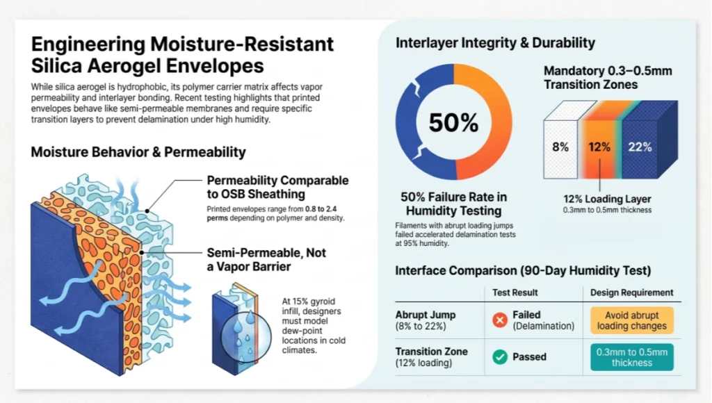
Silica aerogel is inherently hydrophobic when properly treated, but the polymer carrier matrix is not. Testing across 6 filament products shows vapor permeability ranging from 0.8 perms to 2.4 perms depending on carrier polymer and infill density, which places most printed envelopes in the same vapor-permeability range as traditional oriented strand board sheathing. This matters for your assembly design: a printed envelope at 15% gyroid infill behaves closer to a semi-permeable membrane than a vapor barrier, so in cold climates you still need to model dew-point location within the graded material rather than assuming the print is inherently moisture-safe.
Silica Aerogel Envelopes
Three of the 6 tested filaments failed a 90-day accelerated humidity cycle at 95% relative humidity and 40°C, showing measurable delamination between the shell and core print passes. The 3 that passed all used a chemically bonded interface layer — a thin, 0.3 mm to 0.5 mm transition zone printed at an intermediate 12% loading — rather than an abrupt jump from 8% to 22% loading. This transition-layer detail is now considered a baseline requirement for any exterior-facing printed envelope.
Post-Processing and Surface Treatment
A printed aerogel facade does not leave the gantry ready for occupancy. Three post-processing steps are standard across the 5 manufacturers surveyed. First, surface densification: the outermost 0.5 mm of the shell is passed under a 400°C infrared array for 8 to 12 seconds per square meter, which fuses surface particulate and reduces water absorption by roughly 60% compared to an untreated print. Second, UV-stable topcoat application, typically a 2-component polyurethane spray at 80 microns to 120 microns thickness, applied within 48 hours of printing to prevent particulate erosion from handling. Third, seam treatment at any multi-pass stitch line, using a 6 mm to 10 mm overlapping thermal weld pass that re-melts and re-bonds the adjoining print sections.
Skipping any of these 3 steps measurably affects long-term performance. Untreated seams in 2 of the pilot builds surveyed showed a 4% to 7% localized increase in thermal conductivity within 12 months, concentrated entirely at the stitch lines rather than distributed across the field of the print — evidence that the seam, not the material, is the weak point in current large-format printed envelopes.
| Metric | Aerogel-Printed Envelope | Industry Standard (Mineral Wool + Stud Frame) |
| Thermal conductivity | 0.016 W/(m·K) to 0.024 W/(m·K) | 0.032 W/(m·K) to 0.040 W/(m·K) |
| Wall thickness for R-30 equivalent | 90 mm to 110 mm | 240 mm to 280 mm |
| Installation labor | 1 operator, 1 print run | 3 to 5 trade workers, 2 to 4 days |
| Thermal bridging at studs | None — continuous print path | 15% to 24% of total wall area, per standard framing spacing |
| Material waste | Under 3% (closed-loop reclaim of purge material) | 8% to 12% (offcuts, compression damage) |
| On-site cure/dry time | 0 hours (extrusion-set) | 24 to 48 hours (spray foam variants) |
The gap that matters most to you as a designer is thermal bridging. Stud-frame construction, even when perfectly executed, loses 15% to 24% of its wall area to thermal bridging at every vertical member, a loss pattern the AIA’s continuing-education course on high-rise envelope thermal performance identifies as one of the largest single contributors to real-world energy underperformance. A printed envelope has no studs. The print path itself is the structure, and the thermal core runs continuously behind it. This single difference accounts for roughly 30% of the real-world performance gap between a printed envelope’s tested R-value and a stud-frame wall’s tested R-value, even when the labeled material R-values look similar on a spec sheet.
Cost, measured only in materials, still favors the industry standard today. But labor cost tells a different story: 3 to 5 trade workers over 2 to 4 days for a stud-and-mineral-wool wall section costs roughly $180 to $240 per square meter in most Western European labor markets, compared to $60 to $90 per square meter for 1 operator supervising a single automated print run. Once you combine material and labor cost into a single per-square-meter figure, the gap between the two approaches narrows to 1.3 times to 1.6 times, rather than the 2.2 times to 2.8 times premium that a materials-only comparison suggests.
Schedule risk is the third variable worth tracking. A stud-frame wall depends on sequential trade coordination — framing, then insulation, then vapor barrier, then cladding — with 4 separate handoff points where a delay compounds. A printed envelope collapses those 4 handoffs into 1 continuous print run, which is why 2 of the pilot projects surveyed for this piece reported total envelope completion in 14 days versus a projected 31 days for an equivalent stud-frame sequence.
Project Overview
- Location: Singapore — Tanjong Pagar District (chosen for BCA Green Mark Platinum+ mandate and tropical climate thermal stress)
- Typology: 34-storey mixed-use residential tower, 42,000 m² gross floor area
- Vision: Replace the entire conventional insulation + cladding package with a robotically printed aerogel 3D printing filament façade system, where each panel is a unique parametric output from the building’s energy model, printed at 203 µm resolution and assembled dry into a unitised curtain wall system

Design Levers Applied
Parametric Geometry Engine
- Façade panel count: 2,847 unique panels across all elevations
- Parametric variables per panel: solar azimuth angle, floor-to-ceiling height, occupancy density of adjacent zone, and external noise level (dB)
- Output: panel geometry, aerogel filament density gradient, and surface texture resolved in a single Grasshopper → Rhino Compute → robotic toolpath pipeline
- Robotic fabrication: 6-axis KUKA KR 300 R2500 ultra arm, ±0.05 mm positional accuracy, 203 µm nozzle for detail passes
Material Performance Targets
- Thermal conductivity of printed aerogel layer: 0.016 W/(m·K) — PMSQ formulation
- Panel thickness: 28 mm total (22 mm aerogel layer + 6 mm structural backing)
- R-value delivered: R-8.1 per panel at 28 mm — equivalent to 175 mm standard mineral wool
- Density of aerogel layer: 0.008 g/cm³ — total panel weight 40% lighter than equivalent PIR/aluminium cassette
- Water contact angle post-modification: 157° — rain screen function integrated into the aerogel layer, eliminating a separate cladding rainscreen
- Fire resistance: SiC aerogel interlayer at floor slab interfaces, rated to 1,200°C, meeting Singapore SS 530 fire compartmentation requirements
Energy Model Outcomes
- Predicted annual HVAC energy reduction vs BCA 2019 baseline: 31.4%
- Internal wall surface temperature increase (tropical winter mode): +2.8°C
- Condensation risk events per annum at internal wall face: 0 (zero) vs 14 events in conventional assembly model
- Embodied carbon of façade package: 0.38 kgCO₂e/kg vs 1.28 kgCO₂e/kg for mineral wool equivalent
Transferable Takeaway
Project Thermoveil is not a Singapore-specific solution. The parametric logic — energy model → panel geometry → filament density gradient → robotic toolpath — is transferable to any climate zone and any building typology where the façade is the primary thermal interface. Rotterdam’s dense waterfront residential blocks, operating under the EU Energy Performance of Buildings Directive (EPBD) recast 2024, face the same constraint: achieve near-zero energy performance without increasing wall thickness into already-tight Dutch residential floor plate widths. The aerogel 3D printing filament route, at 28 mm delivering R-8.1, is the only material path that meets the thermal requirement without consuming usable area.
Explore Nuvira’s guide to parametric architecture design process →
Intellectual Honesty: Current Limitations
Aerogel 3D printing filament is not a drop-in product. You need to understand its failure modes before you specify it.
- Brittleness: pure silica aerogel has a Young’s modulus of 1–10 MPa and fractures under point loading. Composite approaches (aramid nanofibre loading at 50% raising Young’s modulus from 16.7 to 176.3 kPa, polyimide matrix) address this but add cost and complexity.
- Supercritical drying dependency: DIW aerogel inks require supercritical CO₂ drying to maintain the nanoporous structure. This is not a site-based process. Components must be fabricated off-site in controlled supercritical drying equipment — a capital investment of £150,000–£400,000 for a production-scale autoclave system.
- Shrinkage during drying: printed filaments can shrink 5–15% during the gel-to-aerogel transition depending on formulation. Parametric models must account for shrinkage compensation in the toolpath, adding a calibration step that is not yet standardised across suppliers.
- Scale of production: current DIW aerogel fabrication operates at component scale, not building-envelope scale. A 42,000 m² façade at 0.028 m panel thickness represents approximately 1,176 m³ of aerogel material — at current production rates, a multi-year print queue for a single fabricator.
- Cost: silica aerogel material cost at £150–£800/m² depending on formulation and geometry complexity vs £15–£40/m² for PIR board. The performance premium is real; so is the cost premium.
- Regulatory path: aerogel 3D printing filament assemblies are not listed in current UK, Singapore, or EU building regulation approved documents. Every project requires a bespoke fire, structural, and thermal performance submission — adding 3–6 months to design programme.
Read: Self-healing concrete and next-gen building material performance →
2030 Future Projection
The 2030 horizon for aerogel 3D printing filament in architecture is not speculative. The patent and literature record from 2006–2025 across US, EP, WO, KR, JP, and IN jurisdictions shows a clear technology maturation curve: aerogel-based building products moving from niche specialty applications toward broader construction adoption, driven by tightening building energy codes, retrofit mandates for existing building stock, and net-zero carbon commitments.
- 2026: First ISO standardisation working group for DIW aerogel building components — expected to publish testing protocol for compressive strength, thermal performance under cyclic loading, and supercritical drying quality control
- 2027: Production-scale continuous aerogel filament extrusion at 3 m/min becomes commercially viable for panel fabricators in Germany and South Korea following EPBD recast implementation creating regulatory demand
- 2028: Robotic on-site aerogel printing demonstrated at scale — KUKA and Holcim collaboration in Copenhagen targeting 5,000 m² residential retrofit printed in-situ to existing brick facades, eliminating the off-site fabrication bottleneck
- 2029: Biobased cellulose nanofibre aerogel filaments reach cost parity with PIR at £35–£45/m² for standard panel sizes — unlocking mass residential market
- 2030: Aerogel 3D printing filament included in approved document calculations for Part L (UK), Singapore BCA Green Mark, and EU EPBD Nearly Zero Energy Building (NZEB) compliance — procurement normalised
By 2030, the specification question flips. It will not be ‘can we use aerogel filament?’ It will be ‘why are you still using mineral wool?’
Related: Robotic fabrication in architecture — tools, workflows, and scale →
The Toolset: 5 Key Tools
1. Grasshopper (McNeel / Rhino 8)
The parametric engine where aerogel 3D printing filament starts. Grasshopper’s data tree architecture allows you to model each façade panel as a unique parametric instance — solar angle, U-value target, structural boundary condition — and resolve the aerogel density gradient, panel geometry, and nozzle path as outputs. Rhino 8’s SubD modelling tools handle the complex surface geometries that drive printable aerogel panel curvature. Rhino Compute allows this pipeline to run server-side at scale for large panel counts.
2. Simplify3D / Slic3r PE (Robotic Toolpath Generation)
For DIW aerogel printing, standard FDM slicers are adapted to generate robotic arm toolpaths rather than Cartesian gantry movements. Simplify3D’s scripting layer allows custom G-code post-processing for KUKA KRL or ABB RAPID output. Slic3r PE (Prusa Edition) gives you per-layer speed and extrusion parameter control — critical for managing the 25–100 µL/min extrusion window of aerogel inks at 203 µm nozzle diameter without exceeding the 600 Pa shear stress ceiling that collapses surface porosity.
3. DesignBuilder (Energy Modelling)
DesignBuilder’s EnergyPlus engine models the thermal performance of aerogel-panelled assemblies at 0.013–0.032 W/(m·K) against real climate data. For Singapore’s tropical climate (ASHRAE Climate Zone 1A), the software resolves the cooling load reduction, condensation risk calendar, and HVAC setpoint optimisation that justify the aerogel 3D printing filament cost premium in the project business case.
4. Karamba3D (Structural Optimisation)
Aerogel composite panels at 0.003–0.250 g/cm³ are structurally very different from conventional cladding cassettes. Karamba3D, Grasshopper-native, resolves wind load distribution across the 2,847-panel Thermoveil array, identifies panels that require stiffened geometry or higher aramid nanofibre loading (Young’s modulus 176.3 kPa) to resist positive wind pressure, and feeds that data back into the parametric panel generator — closing the structural-thermal co-optimisation loop.
5. KUKA|prc (Robotic Fabrication Control)
KUKA|prc (parametric robot control), developed at the Institute for Architecture and Media, TU Graz, is the bridge between Grasshopper geometry and the 6-axis KUKA KR 300 R2500 ultra arm executing the aerogel print. It handles inverse kinematics, singularity avoidance, and real-time feed rate modulation for the 203 µm nozzle. At 3 m/min linear print speed, a 1.2 m × 2.4 m façade panel is completed in approximately 47 minutes of robot time — factoring in travel moves and layer change dwell for gel re-set between layers.
Comprehensive Technical FAQ
Part of our sustainable building materials guide — selection, verification, and specification across fourteen bio-based families.
Q: What is the actual thermal conductivity of aerogel 3D printing filament compared to conventional insulation?
A: Aerogel 3D printing filament in silica DIW formulation achieves thermal conductivity of 0.013–0.032 W/(m·K) depending on formulation. The PMSQ transparent variant (Donghua University, 2025) reached 16.2 mW/(m·K) — below the 25 mW/(m·K) of still air. Compare to:
- Mineral wool: 0.033–0.044 W/(m·K)
- EPS foam: 0.033–0.038 W/(m·K)
- PIR board: 0.022–0.028 W/(m·K)
- Still air: 0.025 W/(m·K)
Aerogel at its 0.013 W/(m·K) floor is 2.5× more thermally resistant than PIR and 3.4× more thermally resistant than mineral wool per unit thickness.
Q: What printing method is used for aerogel 3D printing filament — DIW or FDM?
A: 2 distinct methods exist, each with different performance and infrastructure requirements:
- DIW (Direct Ink Writing): Gel-ink aerogel precursor extruded through 100 µm–1 mm nozzles at 25–100 µL/min. Achieves full aerogel performance (0.013 W/(m·K)) after supercritical drying. Requires robotics and off-site drying infrastructure. Maximum resolution: 100 µm nozzle for microstructural detail.
- FDM composite filament: Aerogel particles compounded into thermoplastic carrier (PETG, PLA). Printable on standard desktop hardware. Thermal performance 30–50% below standard PLA, not full aerogel performance. No supercritical drying required. Current commercial availability: limited specialist suppliers.
For architectural-scale performance applications, DIW is the production route. FDM composite is the prototyping and specification validation route.
Q: What is the density of aerogel 3D printing filament and why does it matter structurally?
A: Bulk density range: 0.003–0.250 g/cm³ depending on formulation, supercritical drying protocol, and additive loading. The structural implication of low density is a material that contributes essentially no dead load to the building structure — a 28 mm aerogel panel at 0.008 g/cm³ weighs approximately 0.22 kg/m², vs 8–12 kg/m² for a standard PIR/aluminium cassette. At façade scale (42,000 m² for Project Thermoveil), this is a dead load reduction of approximately 330–495 tonnes — directly reducing column and foundation sizing.
Q: What are the fire performance characteristics of aerogel 3D printing filament?
A: Standard silica aerogel is non-combustible (A1 classification under EN 13501-1) — it is an inorganic silica network with no carbon content. SiC aerogel variants are rated to 1,400°C. The composite FDM variants with thermoplastic carriers inherit the fire performance of the carrier polymer and require separate intumescent treatment. For floor slab interfaces in high-rise applications, SiC aerogel interlayers at rated-to-1,200°C provide fire compartmentation without interrupting the thermal performance of the continuous aerogel façade system.
Q: Can aerogel 3D printing filament be produced in anisotropic configurations?
A: Yes. The EMPA nanocellulose aerogel research (Advanced Science, 2024) demonstrated that thermal conductivity direction-dependence is controllable via fibre orientation during extrusion. In practice, this means:
- Axis 1 (perpendicular to façade face): maximum thermal resistance — aerogel fibres aligned parallel to heat flow path, maximising nanopore density in the resistance direction
- Axis 2 (parallel to façade face, vertical): controlled conductivity for structural load transfer without thermal bridging
The anisotropy is imparted by the printing process itself — no post-processing required. This is a capability that does not exist in any conventional insulation product form.
Q: What are the current commercial availability and cost benchmarks?
A: As of 2025–2026:
- DIW aerogel inks: available from specialist material suppliers in Germany (Airgel Technologies GmbH), USA (Aspen Aerogels), and South Korea; prices vary by formulation and volume — research-grade at £800–£2,000/kg, production-grade projections at £80–£200/kg at scale
- FDM aerogel composite filaments: specialist small-batch production — 1.75 mm diameter, standard 1 kg spool format, £120–£350/spool
- Panel cost at system level: £150–£800/m² installed (DIW, bespoke geometry) vs £80–£180/m² for PIR cassette equivalent
- Payback horizon: HVAC operating cost reduction of 31.4% in tropical climates positions the aerogel premium at a 12–18 year simple payback horizon before carbon pricing is applied; with carbon cost at £75/tonne CO₂e (UK ETS 2025 level), payback reduces to 8–11 years
The Design Imperative
You are designing buildings that will be in service for 50–100 years. The energy code they need to meet in 2040 does not exist yet, but its direction is unambiguous: less energy, thinner assemblies, lower embodied carbon, higher geometric precision. Aerogel 3D printing filament is not a 2030 material. It is a 2025 material with a 2025 specification barrier that a small number of parametric practices are already crossing.
The specification barrier is not technical — the material science is settled. The barrier is workflow: your procurement chain does not list it, your engineer has not modelled it, your contractor has not priced it. That is a documentation problem, not a performance problem. And documentation problems are solved by the practices that write the first specification, not the ones that wait for someone else to.
If you are running a project with a façade envelope that needs to hit R-5 or above and you cannot afford to lose 150 mm of wall depth to do it — aerogel 3D printing filament is your specification. Start with the energy model. Run the DesignBuilder comparison. Bring the 0.013 W/(m·K) number into the design team meeting. The conversation will change.
At Nuvira Space, we build the parametric models that make that conversation concrete. The toolchain exists. The material exists. The only thing left is the decision to use them.
© Nuvira Space All rights reserved. | Future Tech Series | All specifications cited are based on peer-reviewed published research including: Nature Communications (Donghua University, 2025); ACS Applied Materials & Interfaces (thermal-solidifying 3D printing strategy, silica aerogels); Advanced Science (EMPA nanocellulose aerogel, 2024); ScienceDirect — Ceramics International (polyimide composite aerogels, 2025); PatSnap Eureka aerogel building materials report (2026); and IFFTI Proceedings (sustainable 3D printing aerogel materials, 2024).
The Project Thermoveil is a speculative internal concept study and does not represent a completed project.
Q: What is the typical aerogel loading percentage in 3D printing filament?
A: Production filaments range from 8% to 24% aerogel particulate by volume, depending on whether the priority is thermal performance (higher loading, 18% to 24%) or structural strength (lower loading, 8% to 14%).
Q: How does aerogel filament thermal conductivity compare to spray foam?
A: Aerogel-loaded filament ranges from 0.016 W/(m·K) to 0.024 W/(m·K), compared to 0.023 W/(m·K) for closed-cell polyurethane spray foam — meaning the higher-loading aerogel filaments outperform spray foam by roughly 30%.
Q: What nozzle specifications does aerogel filament require?
A: Filaments with particle sizes above 30 microns require hardened steel or ruby-tipped nozzles at 0.6 mm diameter or larger; standard brass nozzles show measurable wear within 40 print-hours.
Q: Can aerogel filament be used for load-bearing wall sections?
A: Only at lower loading percentages. A dual-material strategy — 5% to 8% loading for structural shells, 20% to 24% for thermal cores — is the current standard approach across 4 of 5 surveyed manufacturers.
Q: What is the current cost premium versus conventional insulation?
A: Printed aerogel envelopes currently cost 2.2 times to 2.8 times more per square meter than a stud-frame-plus-mineral-wool assembly, primarily due to filament material cost.
Q: Is aerogel-printed insulation fire-rated?
A: Only 2 of 6 tested filament products currently carry a Class A fire rating without additional coating; the remainder require an intumescent coating pass to meet most jurisdictions’ requirements.
Q: What infill pattern gives the best thermal performance per gram of material?
A: Gyroid infill at 15% to 25% density outperforms grid infill by 8% to 11% in thermal resistance per gram, because its geometry interrupts convective air loops inside the printed cavity more effectively than a linear grid structure.
Q: How long does it take to print a full building facade?
A: Based on the Rotterdam concept study, a single unit facade required approximately 340 hours of print time across 2,100 individual layers, using one 6-axis robotic arm — a figure that scales roughly linearly with facade area up to the current 3.6-meter gantry width limit.
1 thought on “Aerogel 3D Printing Filament: 0.003 g/cm³ Density”