

Table of Contents
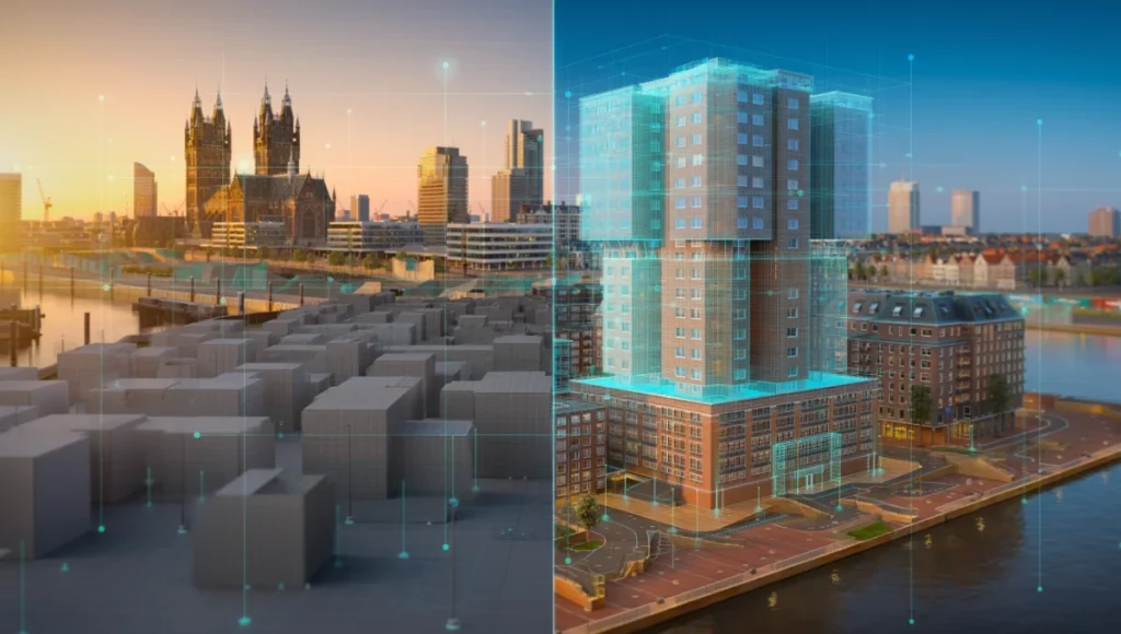
The current trajectory of the AEC industry is undergoing a violent shift away from “clean-slate” digital modeling toward reality-capture integration. The traditional reliance on manual box-modeling for existing site conditions is an expensive, slow, and ultimately inaccurate relic. By mastering photogrammetry architecture, we are no longer approximating the world; we are indexing it with millimeter precision. This macro-observation is critical: as global cities like Rotterdam lead the charge in creating Digital Twins for smart cities for flood defense and urban density management, the individual architect must adopt these same high-fidelity simulation tactics to remain relevant in a data-driven landscape.
Nuvira Perspective
At Nuvira Space, we view the intersection of human design and machine perception as the final frontier of the built environment. We believe that architectural reality is not something to be recreated from scratch, but a complex data set to be synthesized. Our philosophy centers on human-machine synthesis—leveraging Unreal Engine 5 for architectureand high-fidelity photogrammetric simulations to bridge the gap between digital intent and the physical world. We don’t just render; we solve for the atmospheric and structural truth of a site.
Step-by-Step Workflow: The High-Fidelity Pipeline
To move beyond basic mesh generation, you must adopt a rigorous data-acquisition and post-processing hierarchy. This workflow aligns with the AIA Digital Practice Documents (E203™–2013), which provide a framework for establishing the protocols and expectations for the use of digital data on a project.
1. Tactical Data Acquisition (The 80% Overlap Rule)
The success of photogrammetry architecture starts in the field, not the software.
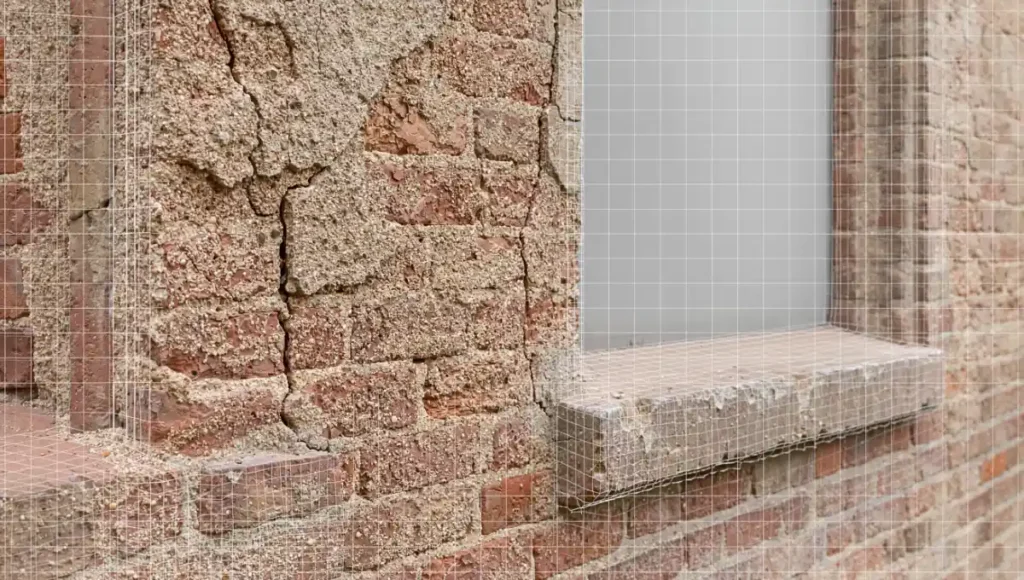
- Sensor Specs: Minimum 24.2MP Full-Frame sensor to avoid noise floor interference in shadow regions. For high-heritage refurbishment, we recommend medium-format sensors (50MP+) to capture the granular decay of masonry.
- Optics: Prime lenses (35mm or 50mm) to eliminate variable barrel distortion found in zooms. Lenses must be calibrated to a fixed focus at infinity to prevent depth-map contradictions during the alignment phase.
- Capture Pattern: A “Orbital + Nadir” hybrid. You need 80% frontal overlap and 60% side overlap. This redundancy is the only way to ensure the SIFT (Scale-Invariant Feature Transform) algorithms can calculate tie points without “drift” over long linear facades.
2. Alignment and Component Breaking
In RealityCapture or Metashape, avoid the “one-click” alignment trap. Large architectural sites often feature repetitive patterns (windows, columns) that cause “mismatches” in the point cloud.
- Grouping: Break complex facades into separate “Components” based on material reflectivity. Scan glass-heavy sections at sunset to minimize specular glare.
- Control Points: Manually anchor at least 5 Ground Control Points (GCPs). These should be surveyed using total station coordinates. Without GCPs, the “bowl effect” (a subtle curvature in the 3D model) will render your site plans architecturally useless for legal planning submissions.
3. Topology Optimization: Retopology for Real-Time
Raw scans are useless in a production BIM environment due to astronomical poly counts ($100M+$ polys).
- Decimation: Use quad-dominant decimation. Unlike standard triangle decimation, quad-dominant meshes preserve the integrity of architectural corners and window reveals.
- Normal Mapping: Bake the high-poly geometric detail into a 16-bit 8K Normal Map. This allows you to run a $50k$ polygon proxy that looks identical to a $50M$ polygon scan, a necessity for smooth navigation in VR/AR environments.
Comparative Analysis: Nuvira vs. Industry Standard
| Feature | Legacy Standard Workflow | Nuvira Photogrammetry Tactic |
|---|---|---|
| Site Context | Manual “Massing” blocks based on 2D maps. | Georeferenced, sub-centimeter digital twins. |
| Texture Fidelity | Tiled procedural shaders (look “CG”). | Decal-based, location-specific PBR textures. |
| Global Illumination | Baked lightmaps (static, non-reactive). | Real-time Lumen/Ray-tracing on scanned assets. |
| Speed | 2-4 weeks for complex site modeling. | 48-72 hours from flight to optimized mesh. |
| Legal Compliance | Approximate drawings (subject to error). | AIA-compliant digital site records. |
Concept Project Spotlight: Speculative / Internal Concept Study “The Rotterdam Nexus” by Nuvira Space
Project Overview: Rotterdam / Urban Infill / Carbon-Neutral Hub
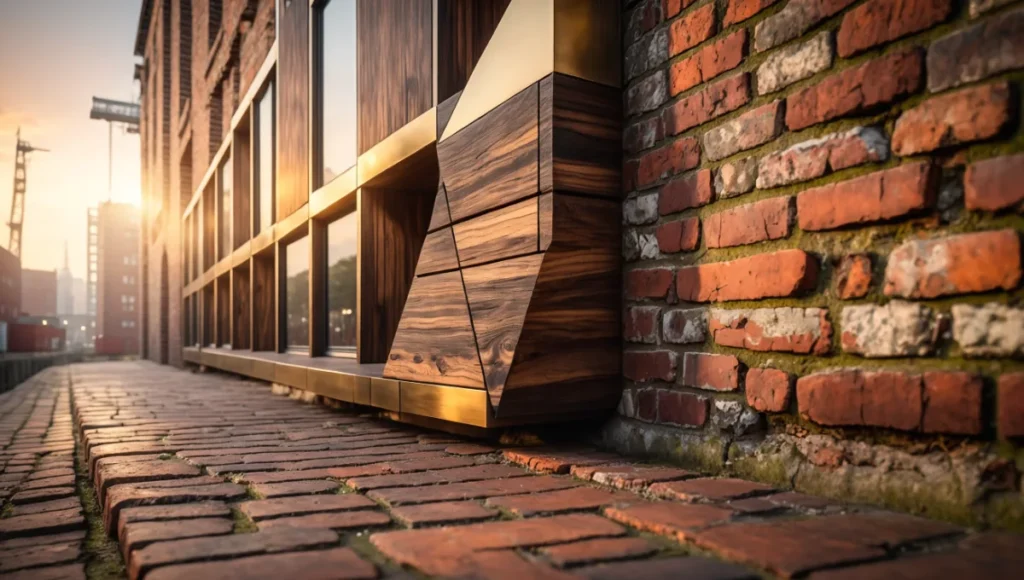
This study explored the integration of a modular timber structure into a highly complex, 19th-century industrial brick corridor in Rotterdam’s port district. The challenge was the extreme irregularity of the existing masonry, which featured centuries of settling and structural shifting.
Design Levers Applied
- Material Matching: We utilized terrestrial photogrammetry to scan the specific weathered brick. This data was fed into our robotic fabrication in architecture pipeline to pre-cut timber joints that fit the irregular wall surface with 2mm tolerances.
- Lighting Specs:
- HDRI Calibration: 32-bit radiance maps captured on-site at 12:00 PM and 6:00 PM.
- Lumen Integration: The scanned mesh acted as a high-precision light bouncer, ensuring the new timber structure received accurate “color bleed” from the existing brickwork.
Transferable Takeaway
Integrating new designs into scanned “Reality Assets” provides immediate visual credibility. For architects presenting to heritage boards, showing a “digital twin” of the existing site alongside the intervention removes the “fear of the unknown” often associated with modern design in historic contexts.
Intellectual Honesty: Hardware Check
Professional-grade photogrammetry is a “brute-force” computational task.
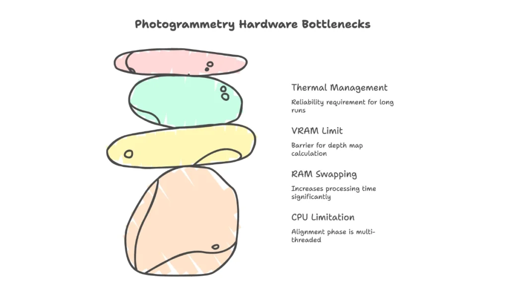
- CPU: Threadripper or high-core count i9/Ryzen 9. The alignment phase is heavily multi-threaded.
- RAM: 128GB DDR5. If the software “swaps” to the hard drive during mesh construction, processing time can increase by 1000%.
- GPU: NVIDIA RTX 4090 (24GB VRAM). The VRAM limit is the primary barrier for the “Depth Map” calculation phase.
- Thermal Management: These machines will run at 100% load for 24+ hours. Liquid cooling is not a luxury; it’s a reliability requirement.
2030 Future Projection: The End of “Modeling”
By 2030, we predict the role of the “3D Modeler” will evolve into the “Data Curator.” Neural Radiance Fields (NeRFs) and Gaussian Splatting will replace mesh-based photogrammetry, allowing for real-time volumetric navigation of sites with perfect transparency and reflection handling. The AIA is already looking at the Standard Form of Agreement Between Owner and Architect for Digital Data Management, which will soon include clauses for “Real-Time Site Fidelity” as a contract deliverable.
Secret Techniques: Advanced User Guide
Tactic 4: The Polarizing Filter Hack
To eliminate “specular highlights” (sun glints) on windows—which cause “spikes” in the 3D geometry—use a circular polarizer. This results in “flat” textures that allow you to re-light the model dynamically in post-production without “baked-in” shadows that break the illusion during different times of day.
Tactic 5: Cross-Polarization for PBR Extraction
If you are scanning specific materials for use as assets, use a cross-polarized flash setup. This separates the Diffuse (Albedo) from the Specular (Gloss) map. You can then import these into a PBR material graph to create a surface that reacts perfectly to the sun’s movement in your engine.
Tactic 6: Shadow Casting via Proxy Geometry
When rendering, the scanned site should not just be a background. It must be a “Shadow Catcher.” Ensure your Global Illumination is set to “Ray-Traced” with at least 8 bounces. This captures the “Ambient Occlusion” in the microscopic cracks of the scanned site, making the new 3D model look “seated” rather than “floating.”
Tactic 7: Spectral Denoising in Post
Process your raw images through a dedicated AI denoiser (like Topaz Photo AI) before alignment. By removing sensor noise while keeping the edges sharp, the photogrammetry software can find significantly more “Features” in low-light shadow areas, resulting in a mesh that doesn’t “break” in the corners.
Comprehensive Technical FAQ
Q: Why does my mesh look “melted” on vertical surfaces?
A: This is “Gimbal Angle” error. If the camera only looks down (Nadir), it cannot “see” the underside of cornices or the depth of window reveals.
- Fix: Ensure you are taking “Oblique” shots (45 to 60-degree angles).
- Spec: Aim for a “Triple-Ring” orbital pattern: one at 10m altitude (30 degrees), one at 20m (45 degrees), and one at 30m (60 degrees).
Q: How do I handle glass and reflective surfaces?
A: Photogrammetry fails on mirrors and transparent glass because there are no “features” for the software to track.
- Tactic: Spray highly reflective areas with a removable “scanning spray” (cyclododecane) to create a matte, trackable surface, or manually “blank out” the glass in post and replace it with a real-time refractive shader.
Q: Is photogrammetry legally defensible for site surveys?
A: Yes, if conducted under the supervision of a licensed surveyor and tied to georeferenced benchmarks. Refer to the AIA Document C106™–2013, Digital Data Licensing Agreement, for the transfer of such data between parties.
Upgrade Your Vision: The Nuvira Consultation
The transition to photogrammetry architecture is not just a software upgrade; it is a total shift in professional standards. If your firm is still drawing existing conditions by hand, you are operating with a margin of error that is no longer acceptable in the age of Digital Twins.
[Contact the Nuvira Visual Lab to implement these tactics on your next Tier-1 project and redefine what is possible in architectural simulation.]