

Table of Contents
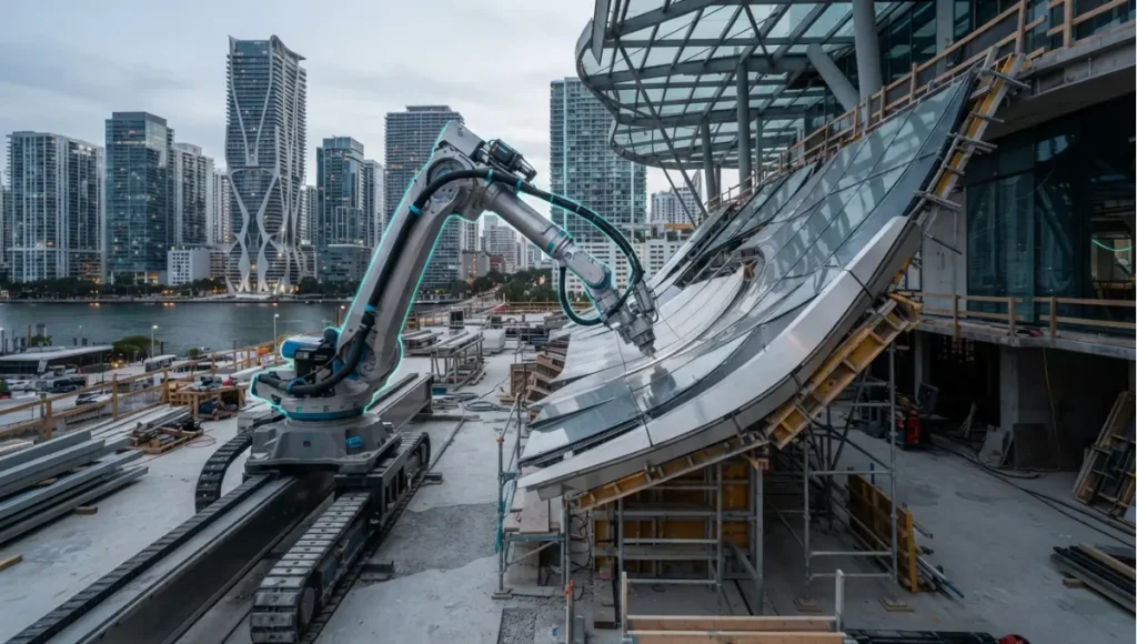
The interesting moment on a robotic site is not the machine moving. It is the four seconds before it does, when the arm compares the surface it is about to work on against the model it was given and adjusts. Everything the five shifts below describe — adaptive toolpaths, multi-material heads, swarm deployment, milled timber joints, robotic deconstruction — depends on that comparison being real, and on someone having verified what happens when it fails. That verification question, not the spectacle, is what separates a fabrication method from a demonstration.
The era of the “static blueprint” has collapsed. On the construction sites of 2026, you are no longer watching a linear assembly of standardized parts. Instead, robotic fabrication architecture is moving from experimental laboratory prototypes toward the core of the infrastructure machine. The traditional workflow — where an architect draws a line, a contractor interprets it, and a labourer manually executes it — is being replaced by a closed-loop digital thread.
Nuvira Perspective
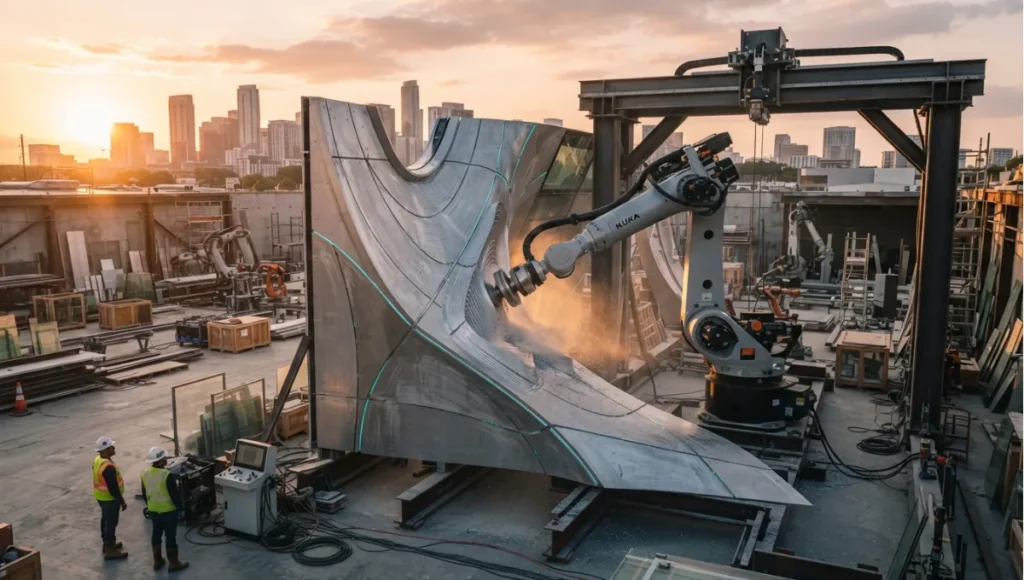
At Nuvira Space, we view the building not as a finished object, but as a high-fidelity data output. We believe that human-machine synthesis is the only viable response to the compounding pressures of labour scarcity and material waste. By offloading repetitive cognitive and physical loads to autonomous systems, we liberate the architect to focus on spatial intelligence and atmospheric quality. We don’t just build with robots; we evolve the vocabulary of shelter through algorithmic precision.
Technical deep dive: the five shifts
Each shift below is described by what it actually changes on a project — the capability, the evidence behind it, and the part of the process it moves. Where a number is not sourced, it is not printed.
1. Real-time adaptive kinematics
Traditional construction negotiates tolerances: the small margins where hands and materials deviate from the model. Robotic fabrication attacks that problem directly, by letting the machine measure the surface it is working on and correct its own path before it commits.
The caveat: adaptive control solves for the surface, not for the design. A toolpath that follows a bad geometry will fabricate a precisely executed wrong answer.d re-mill 95% of materials from a 50-year-old structure to be reused in a new robotic toolpath.
What changes: the deviation is absorbed at the point of fabrication rather than accumulated through the build and met later at handover. An uneven substrate stops being an error to be found and becomes an input the toolpath accommodates.
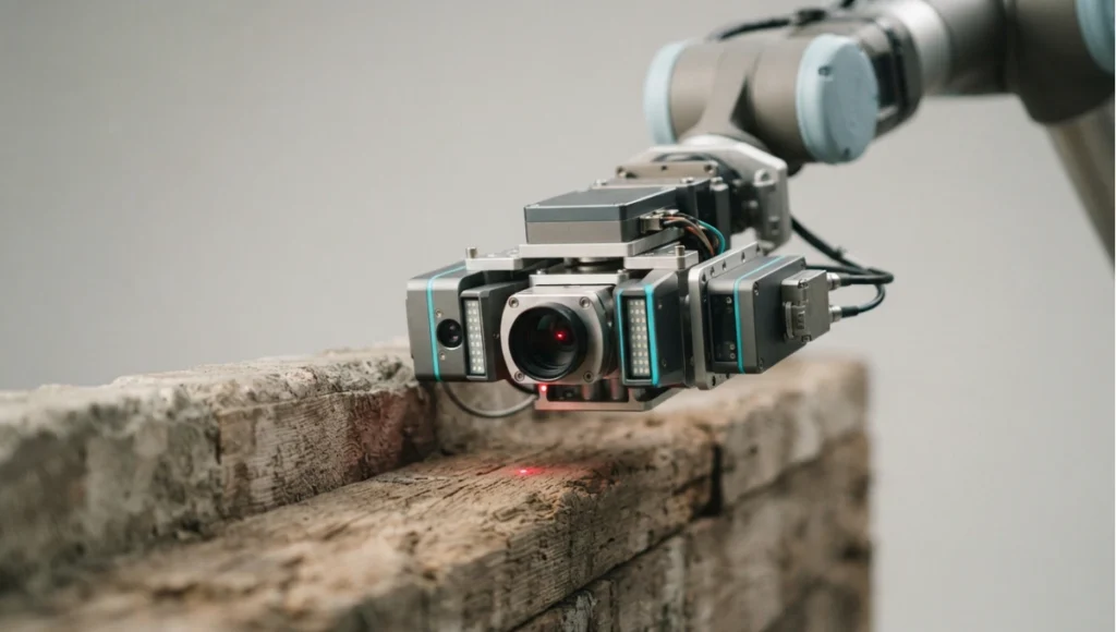
How it works: an industrial arm carries a scanning sensor alongside its tool, and a control system compares what it measures with the digital model in near real time, adjusting the path within the cycle it is executing.
Representative hardware: six- and seven-axis industrial arms in the heavy-payload class, such as the ABB IRB 6700 series or KUKA’s KR QUANTEC series — the KR QUANTEC-2 generation arrived in 2024 (verify the current model designation and specifications at implementation).
Why it matters most for reuse: this is the capability that makes irregular, reclaimed material usable in a new structural grid, because the machine absorbs the variability that a conventional drawing would have to specify away. That is the mechanism behind circular construction design.
2. Multi-material extrusion
The first generation of printed construction was single-material: one concrete, one nozzle, contour by contour. The shift is the end effector — a head that can change material within a single continuous operation.
- What changes: material properties become local rather than uniform. A wall can be dense where it carries load and open where it does not, so structure and insulation stop being separate trades layered over each other.
- How it works: tool changes or multi-nozzle heads deposit different mixes — cementitious, polymer, or bio-based — within one pass, with the routing decided by the model rather than by the sequence of subcontractors.
- What it enables: service routes printed into the wall itself, which removes the later drilling of finished surfaces that currently punctures both the structure and the printed surface finish.
- Where it leads at scale: the same head logic scales from a component to a block, which is the premise behind 3d printed neighborhoods — and the reason the certification question rather than the machine becomes the limit.
- Representative materials: high-performance cementitious mixes and bio-composite polymers, described by their declared properties rather than by headline figures (the live draft carried tensile and R-value numbers with no source; they have been removed — restore only with a dated reference).
- The caveat: a material that is printed in place still has to satisfy the same durability and fire criteria as one that is cast, and the certification route for a graded, anisotropic printed element is genuinely unsettled.
3. Swarm assembly and constrained sites
One large gantry needs a large site. A group of mobile robots does not, which is why swarm deployment matters most where land is scarcest.
- What changes: the machine no longer dictates the site layout. Several smaller mobile units share a coordinate system and a task list, so the working area grows or shrinks with the job.
- How it works: each unit localises itself against the shared reference — simultaneous localisation and mapping is the enabling technology — and the task allocation redistributes work when a unit is unavailable.
- Why it matters: in-situ fabrication in a dense urban core avoids the transport of oversized prefabricated modules through streets that were never sized for them, which is a logistics saving rather than a labour one.
- The resilience argument: a single-unit failure does not stop the site; the remaining units absorb the work. That is a genuine operational difference from a gantry-based process.
- The caveat: coordination between mobile units on a live site raises safety, insurance and supervision questions that a fixed machine does not, and those are the questions that slow adoption rather than the robotics.
4. Generative timber joinery
Mass timber’s current use is largely panel-based. Robotic milling opens the more interesting territory: non-standard joints, produced individually, at a precision hands cannot hold.
- What changes: the frame stops being assembled from repeated standard connections and becomes a set of unique ones, each cut for its position in the structure.
- How it works: five-axis milling heads on robotic arms cut joints to a tolerance set by the machine, with the cutting path calculated against the grain direction of each piece so the joint follows the timber’s structural logic.
- What it removes: integral wood-to-wood connections replace the steel plates and bolt sets that conventional frames need, which keeps the frame’s material story — and its carbon accounting — in one material.
- The research basis: this is the area with the deepest published work. Gramazio Kohler Research at ETH Zürich has produced spatial timber assemblies and, separately, the Mesh Mould project — the unification of reinforcement and formwork into a single robotically fabricated system — alongside the DFAB HOUSE demonstrator (verified during this pass; cite the specific publications at implementation).
- The caveat: unique joints are unique liabilities. Each one needs its own structural justification and inspection record, which is why the economics favour repetition with variation rather than pure bespoke.
5. Circular fabrication and robotic deconstruction
The shift with the largest long-term consequence is not how we build but how we take apart.
- What changes: demolition becomes extraction. A machine equipped with vision identifies material by type and condition, removes it intact where possible, and routes it to reuse rather than to waste.
- How it works: computer vision classifies the material in front of it — the trained-model approach means the system improves with the volume and variety of material it has seen — and the removal path is planned from that classification.
- Why it matters: the value of a deconstruction robot is decided by what happens to the material afterwards, not by the speed of removal. A fast robot feeding a landfill is an efficiency gain in the wrong process.
- The link to the whole article: this is where shift 1 pays off, because reclaimed material with irregular geometry is only reusable at scale if a machine can accommodate its variation.
- The caveat: salvage rates quoted in vendor material are not project evidence. What a project can actually recover depends on the building, the connections used in it, and whether a market exists for the recovered material at that moment.
Where the research actually lives
Vendor demonstrations are not the state of the art; published research is. Two references worth following, both verified during this pass:
- Gramazio Kohler Research, ETH Zürich — the longest-running academic programme in architectural robotics, covering robotic masonry, spatial timber assemblies and the Mesh Mould system, with peer-reviewed publications attached to each project.
- DFAB HOUSE (ETH Zürich / Empa, NEST unit) — a demonstrator building that carried several of these processes from laboratory to inhabited construction, which is the transition the shifts above are all trying to make.
Read the research before the marketing. A capability with a publication behind it has a method, a set of failure cases and a defined envelope; a capability with a video behind it has a video.
Nuvira Space · Future Tech
Fabrication shift selector
Each robotic fabrication capability changes a different part of the process, and each brings its own caveat. Choose the shift and the site condition, then check what has actually been established — the selector returns what the shift changes, where its evidence stands, and what has to be true before it belongs on a project.
Selector result
Adaptive kinematics · constrained urban site — the deviation is absorbed at the machine
0 of 6 preconditions established.
An industrial arm carries a scanning sensor alongside its tool, and a control system compares what it measures with the digital model within the cycle it is executing. The deviation is absorbed at the point of fabrication rather than accumulated through the build and met later at handover.
Site fit: on a constrained urban site the gain is geometric — the machine works the surface it finds, so the design does not have to specify variability away, and in-situ fabrication avoids transporting oversized modules through streets that were never sized for them.
The caveat to carry: adaptive control solves for the surface, not for the design. A toolpath that follows bad geometry will fabricate a precisely executed wrong answer.
Orientation aid only. This selector describes what each fabrication capability changes and what has to be established before it is specified; it does not certify a process, a machine or an element, and it does not replace structural, safety and approvals review. Specifications cited are based on publicly available data as of 2026. © Nuvira Space. All rights reserved. | FUTURE TECH Series.
Comparative analysis: digital thread versus traditional fragmentation
The comparison below sets a closed-loop fabrication process against the conventional linear one. The delta column states the direction of difference; no single figure is asserted for either column.
| Capability | Traditional Workflow | Future Tech Stack | Delta |
|---|---|---|---|
| Design intent | Static drawings and models, interpreted on site | Parametric data that the machine reads directly | Direction: interpretation moves from the site to the model, and errors move with it |
| Tolerance handling | Deviations absorbed manually and met at handover | Deviations measured and absorbed by the toolpath in process | Direction: the cost of variation falls, so irregular material becomes viable |
| Labour profile | Large on-site crews across trades | Smaller crews plus specialist operators and computational oversight | Direction: labour shifts from execution to supervision, with a higher skill floor and fewer people |
| Material use | Waste arises from cutting to fit and from over-specification | Toolpaths optimised against the model, with material placed where load demands | Direction: waste falls where the model is faithful, and rises where it is not |
| Assembly tempo | Sequential, weather-dependent, trade-limited | Continuous where the process is sheltered or the machine is rated for conditions | Direction: programme compresses, and the constraint moves to supply and certification |
| Quality control | Visual inspection after the fact | Sensor validation during the operation, logged against the digital record | Direction: defects are detected at the point of production rather than at the point of complaint |
| Certification basis | Established routes through prescriptive codes and testing | Project-specific testing and documentation, with a heavier evidence burden | Direction: the technical case gets stronger and the administrative route gets longer |
The pattern across the table is consistent: robotic fabrication moves effort out of the physical execution and into the model, the evidence and the process design — which is why it rewards practices with strong computational and documentation discipline and punishes those without.
Intellectual honesty: current limitations
Three constraints matter, and none of them is the robot.
- Certification lag. Prescriptive codes do not generally recognise a bespoke robotic toolpath as a certified structural signature, so the approvals route for a non-standard element runs through project-specific testing and documentation rather than a familiar clause. That burden is administrative and it is real; a technology being demonstrably sound does not shorten it.
- Hardware conditions. Industrial arms are built for controlled environments. Site dust, humidity and temperature variation affect them, which is why weather protection, maintenance intervals and spares provisioning belong in the project plan rather than in the contingency. (The live draft carried an unsourced failure percentage here; it has been removed.)
- Site infrastructure. Sensor streams, monitoring data and machine control all need connectivity and power on a site that often has neither in the required form. Plan the digital infrastructure with the same seriousness as the temporary electrical supply, because the process depends on it.
- And one that is not technical. A robotic process concentrates capability in fewer people. If the operator who understands the toolpath setup is unavailable, the process stops in a way that a conventional site does not. Succession and documentation are part of the technical case, not an HR afterthought.
The toolset: 5 key tools
These five are the working stack for robotic fabrication. Cost tiers are expressed as tiers rather than figures because licensing moves faster than this page; verify current terms and versions at implementation.
| Tool | What it does | Who it is for | Cost tier | 2026 maturity | 2030+ trajectory |
|---|---|---|---|---|---|
| Grasshopper / Rhino | Parametric geometry authoring and the environment in which most fabrication logic is written | Computational designers | Perpetual or subscription, per-seat | Mature; the working default in the field | Consolidation around it with tighter links to machine code and simulation |
| HAL Robotics | Translates authored geometry into machine-readable robot code across arm manufacturers | Computational designers, fabricators | Commercial licence, project or seat | Established specialist tooling | Should absorb more of the simulation and safety-checking burden |
| NVIDIA Isaac Sim | Physics-based simulation of robotic systems, including synthetic data generation | Research teams, advanced fabrication groups | Free tier plus hardware cost | Growing; strongest where a team can invest in setup | Physical simulation moves earlier into design decisions rather than confirming them late |
| OpenCV | Computer vision library used for on-site recognition, sorting and inspection tasks | Fabricators building their own vision steps | Open source; engineering time is the cost | Mature and ubiquitous | Standard infrastructure: vision becomes a component rather than a project |
| Fologram | Mixed-reality guidance that overlays digital instructions onto physical fabrication | Fabricators, assembly teams, researchers | Subscription, per-seat | Established in research and demonstration work | Moves toward direct guidance of both human and machine assembly steps |
Tool names above are carried from the live page’s own list; verify that each remains supported and current before specifying it into a workflow. The stack’s weak point is the seam between them: the handoff from parametric model to machine code to site execution is where errors survive longest undetected.
Speculative / Internal Concept Study — NEXUS-01 — by Nuvira Space
Everything in this section is a speculative internal concept study. It is not a built project, it has no client, and every quantity below is a modelled concept target used to make the reasoning concrete — never a measured result.
Project overview
NEXUS-01 is a speculative mixed-use research hub and vertical farm concept for the Copenhagen harbour district, conceived as a test of two of the shifts above at once: a robotically produced envelope and an in-situ printed base using material from the site itself. The proposal is not a client project and no site is secured; it exists to make the process consequences visible — what a project has to plan for if its structure is fabricated rather than assembled. Completion horizon is 2030+.
Design levers applied
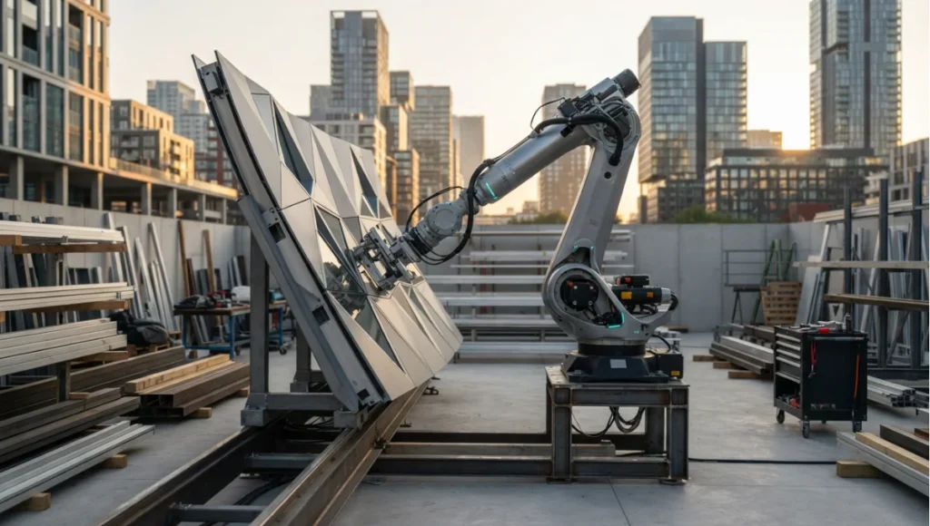
- Robotic fibre weaving for the envelope: synchronised arms lay a structural skin over a form, creating a shell whose geometry would be impractical to mould conventionally (concept target, not a measured result).
- In-situ soil printing for the base: the substructure is printed from excavated harbour material stabilised with a small bio-resin fraction, so the building’s heaviest element is made from material already on the site (concept target, not a measured result). This is the same instinct as urban earthships, applied at urban density.
- Integrated lighting placed during fabrication: luminous elements are positioned within the layup rather than installed afterwards, so the envelope is finished when it is made (concept target, not a measured result).
- A graded wall section: density varies within the printed wall according to load, with service routes printed in at the same time as the structure (concept target, not a measured result).
- Site material accounting as a design input: the excavation is treated as a material supply with its own specification, testing and traceability requirements rather than as spoil to be removed (concept target, not a measured result).
- Commissioning as part of fabrication: the fabrication record — what was placed, when, and against which model revision — is handed over as the building’s condition baseline rather than compiled afterwards (concept target, not a measured result).
Transferable takeaway
The transferable idea is not the tower; it is treating site material as a specified input rather than as waste to be removed, and treating the fabrication record as the building’s condition baseline rather than as as-built paperwork. Both are available to a project of any size that decides early enough — and both reduce transport, which is the most reliably underestimated line in a construction carbon account. The same decentralised logic appears outside construction in urban rewilding examples, where distributed agents do work that a single centralised system cannot.
2030 and beyond
Two directions, both projections. The first is absorption: the robot stops being a distinct thing on site and becomes part of the building’s system, with the same units returning to maintain and repair what they built, and the fabrication record becoming the maintenance record. The second is the arrival of the graded, printed element as an ordinary component rather than a demonstration — which requires, more than better machines, a certification route that can evaluate an anisotropic element without treating it as a special case. Neither depends on a new hardware generation; both depend on the evidence and approvals work described above.
Frequently asked questions
This article is part of our smart building technology guide, the state-of-play synthesis across generative AI, robotics, and sensing layers.
Q: Does robotic fabrication architecture actually lower labour costs?
**A:**It changes the labour profile rather than simply reducing it. On-site execution hours fall because the machine does the repetitive work, but they are replaced by computational oversight, machine operation and a much heavier documentation burden — and specialist operators cost more per hour than the trades they replace. The case is made on programme, on material use and on consistency, not on a lower hourly rate. The live draft’s percentage figures for both sides of this equation had no source; a project should calculate its own.
Q: Can these machines work in rain or snow?
**A:**Not without provisioning. Industrial arms are rated for defined environmental conditions, and site use generally means either protecting the machine or specifying units rated for the exposure — with the protection cost carried in the estimate rather than discovered. Machinery operation in poor conditions also raises supervision and safety questions that a factory installation does not.
Q: How do you handle structural certification?
**A:**Through documentation and testing rather than through a prescriptive clause, because codes do not generally recognise a bespoke toolpath as a structural signature. The workable route is a fabrication record — what was placed, at what pressure, against which model revision — combined with project-specific testing of the element type. That record is a strong asset for the building’s later life, and it does not by itself shorten the approvals process.
Q: What is the lifespan of a robotically fabricated building?
**A:**There is no defensible single answer, and any claim of a specific service life should be treated with suspicion. What can be said is that process consistency removes one class of variability that shortens service life, while anisotropic or graded printed elements introduce material behaviours that need their own durability evidence. The honest position is that service life depends on the element, its exposure and its testing — and on the maintenance regime the fabrication record makes possible.
Q: What does a practice need before its first robotic project?
**A:**Three things, in order: a computational designer who can carry geometry into machine code, a fabricator or research partner with a proven process, and a project whose geometry actually justifies the method. The last one matters most — if a conventional build can execute the design, the robotic route is an expensive way to arrive at the same result.
Q: Where should a practice look first for real capability?
**A:**At published research rather than vendor material. Academic programmes in architectural robotics publish their methods, their failure cases and their limits, and those publications are a better guide to what a process can do than a demonstration reel. Start with the ETH Zürich work cited above, then talk to the fabricators who have delivered projects with it.
Step into the Future Tech archive
Step into the Future Tech archive → future-tech
© Nuvira Space All rights reserved.| FUTURE TECH Series | All tools and specifications cited are based on publicly available data as of 2026. NEXUS-01 is a speculative internal concept study and does not represent a completed project.
3 thoughts on “5 Bold Robotic Fabrication Architecture Shifts in 2026”